|
Examining Evidence for Secondary Use on Historic Glass Associated with the Possible Landing Site of Amelia Earhart and Fred Noonan on Nikumaroro Island
Geoffrey Cunnar
Abstract
This report describes the results of analyses conducted on eight glass shards collected by the International Group for Historic Aircraft Recovery (TIGHAR) from Nikumaroro Island in the Pacific. The glass shards were collected in the context of what might be the final landing site of Amelia Earhart and Fred Noonan who disappeared over the Pacific on July 2nd, 1937. The shards were examined for evidence of post-depositional surface modification and deliberate secondary use. All shards have been modified to various levels by natural physical and chemical processes. Several exhibit features that are indicative of secondary use.
Introduction
The International Group for Historic Aircraft Recovery (TIGHAR) has an ongoing research project on Nikumaroro Island in the Phoenix Island Group in the Pacific Ocean. The project has been documenting the probable landing site and possible encampment of Amelia Earhart and Fred Noonan (Gillespie 2006; King, et al. 2001). During their survey and excavation of the island, TIGHAR researchers encountered and collected broken glass shards amongst other historic artifacts that are evidence for Earhart and Noonan’s occupation of the island. This analysis consists of an examination of those shards and attempts to answer an important question. Is there evidence for secondary use on any of the shards?
Brief Overview of Relevant Use-Wear Research
In the last 40 years extensive research has been published concerning the documentation and description of edge wear of stone tools. This research is pertinent to the research question examined in this paper because experimentation has demonstrated that, in general, edge-wear scar morphology on isotropic materials such as obsidian and glass can be indicative of the hardness of the materials being worked (Akoshima 1987; Odell 1979; Tringham, et al. 1974). Experimentation has also demonstrated that there are many variables that can contribute to the nature of flake attrition along the edge of a tool. These variables can include material type (both tool and contact), force of effort, motion type, edge angle and angle of use. In general, the working of softer materials tends to produce scalar scars. The working of harder materials generally results in the destruction of scalar scars via the production of larger step scars (Tringham, et al. 1974:189-191). Working of medium materials, such as scraping hard wood, can result in a combination of scar types (Akoshima 1987:76-77). When tools are used in a longitudinal motion (such as sawing), edge attrition tends to be located on both sides of the edge. When tools are used in transverse motions (such as scraping) the edge damage is almost always located on one side of the edge only (Odell and Odell-Vereecken 1980:98-99). Over the last 40 years numerous use-wear experiments have been conducted and the results published. This research has made it possible for the general identification of certain activities based on characteristic flake scars. These activities include such tasks as sawing/slicing wood, sawing/slicing bone or scraping wood/bone. Other actions which typically can be identified include graving, boring, chopping, abrading, and pounding (Odell and Odell-Vereecken 1980). Experimentation has also demonstrated that certain butchering and hide working activities leave characteristic use-wear (Frison 1979; Hayden 1979a; Juel Jensen and Peterson 1985; Odell 1980). For example, experimentation on hide scraping has indicated that one of the key identifiers of the activity is severe edge abrasion and rounding (Hayden 1979b).
In addition to the flake attrition, distinctive polish that can form along the edge of a tool has also been correlated with certain material types and motions (Aoyama 1996; Grace et al. 1985; Keeley 1980; Semenov 1970; Vaughn 1985; Yamada 2000). Typically, low power use-wear examination is very useful in obtaining a general idea of the hardness of the material being worked and, to some extent, the motion of the tool. High power observations (typically 150-400X) of the polish formation along the edge or faces of a tool can often reveal the type of material (skin, bone, wood, plant) that the tool last came into contact with. The examination of use-wear polishes is far from being straightforward and studies have not linked polish formation to strictly glass artifacts. There are a host of variables that can severely limit or impact the preservation of use-related polish on stone tools. Some of the most commonly encountered variables are rock type and duration of use. Tools typically must be used for more than just a few minutes to develop a characteristic use-polish (Vaughn 1985). Polish also seems to accumulate on certain rock types more readily than others. Another major limiting factor of high power use-wear studies is being able to identify any post-depositional surface modifications that might have influenced or altered the polish preservation (Holmes 1987; Levi Sala 1986). Given the paucity of studies related to polish identification on glass, this study does not focus on the identification of polish, but does focus on the identification of linear features along the edge. Such features can be indicative of tool motion.
Consideration of Post Depositional Surface
Modification (PDSM) and Other Factors Influencing Use-Wear
The interpretation of use-wear attrition and polish formation is far from being straightforward. The edges of tools can be modified by a number of post-use factors. These factors are commonly referred to as “post depositional surface modification” or PDSM. These modifications can be caused by numerous factors such as rock on rock abrasion, human or animal trampling, numerous interactions between the stone tool and various chemicals in the soil, soil movement wind, sunlight and other factors (Flenniken and Haggerty 1979; Keeley 1980:28-35; Levi Sala 1986; McBrearty, et al. 1998; Stapert 1976; Tringham, et al. 1974; Vaughn 1985:41-44). Tools affected by PDSM often have a background sheen or bright spots (Keeley 1980; Levi Sala 1986:28-35; Stapert 1976). Polish formed on the edges during use can also be removed or reduced in intensity by soil abrasion (Levi Sala 1986:241).
Trampling is of particular concern in this study as the edge damage from trampling can closely mimic wear patterns caused by deliberate utilization (Young and Bamforth 1990). Both animal (Bordes 1961; Lopinot and Ray 2007) and human (McBrearty, et al. 1998) trampling have been described as sources for edge modification on stone tools. Trampling experiments have demonstrated that the associated flake patterning in location, size and orientation is generally random (Flenniken and Haggerty 1979; Nielson 1991; Tringham, et al. 1974). Tringham identified elongate (longer than wide) and unifacial flake scars as being characteristic of trampling. Subsequent research has indicated that the depositional environment, particularly the nature of the substrate, can influence whether trampling scars are unifacial or bifacial, how many scars are produced and whether scars are elongate or broad (Gifford-Gonzalez, et al. 1985; McBrearty, et al. 1998). Pryor (1988), Gifford-Gonzalez (1985) and Nielson (1991) conducted human trampling experiments with obsidian (which closely resembles glass). They concluded the trampling flakes were sparse and randomly distributed. Gifford-Gonzalez concluded that experiments in sand produced more flakes that were elongate than experiments in loam (Gifford-Gonzalez, et al. 1985:815). They speculate that this could be due to more free impact events in sand and more compression events upon loam. Pryor also observed trampling scars were both bifacial and broad. Nielson observed that several specimens that were trampled on a dry substrate yielded scars that could be mistaken for deliberate retouch (Nielson 1991:500).
Another process that can alter the surface of these glass shards is abrasion caused by sand wear (wind driven) and abrasion caused by water wear (tumbling in beach environment). These effects have been studied for stone tools. Davis (1967:348) identifies three characteristics to identify stone tools that have been altered by sand abrasion: 1) the edges have been given opposite bevels, 2) the basins of flake scars have been hollowed out, while ridges are accentuated, 3) phenocrysts and other soft spots have been hollowed into pits. Davis identifies “rounding and smoothing” as being indicators of water wear (Davis 1967:348).
In addition to the physical processes of surface degradation described above, the composition of antique glass and the different chemical constituents could affect the rate and type of weathering. The chemical components in all glass fragments are most likely undergoing complex chemical modifications through time. These changes could be altered by the physical location of the specimen. Water’s influence on the degradation of glass has been well documented for submerged ancient Roman glass (Dal Bianco, et al. 2005).
The processes behind the formation of the iridescent layering observable on antique glass are the subject of much research (Newton 1971). Branda (1999) has examined pitted shards of Roman glass from Baia, Italy and proposed that the circular and vermicular like pitting and bubbles seen in the thin, crusted Roman shards is a product of weathering. More specifically hydrolysis and condensation reactions give rise to a multi-layered glass structure, pore formation and resultant pits and bubbles. Such chemical processes could very likely be altering both the surface and edges of the antique glass specimens from Nikumaroro Island. All of the above PDSM processes have combined to make the identification of secondary use-wear attrition and polish formation on the glass specimens from Nikumaroro extremely difficult. PDSM is discussed in the context of each of the shard descriptions below and summarized in the conclusions of the report.
Analytical Methods
The glass shards examined in this study were first photographed with a macro-photographic setup with a Nikon digital camera. The shards were then observed using a Nikon stereo microscope at magnifications up to 40X. Areas of possible use-wear were documented with an attached Nikon digital camera. The surface and edges of the glass shards were also examined using an Olympus metallurgical microscope outfitted with Nomarski (Wollarston) prisms and capable of magnification in excess of 250X. Similarly, areas of possible use-wear were documented with an attached Nikon camera. In some cases, observed edge attrition was compared to obsidian flakes utilized for a variety of tasks. These flakes are part of the author’s extensive use-wear type collection. Obsidian or “volcanic glass” exhibits similar isotropic properties and conchoidal fracturing characteristics as glass.
Analytical Results
Specimen 2-9-S-78 General Description
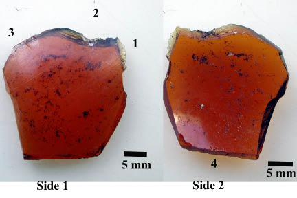
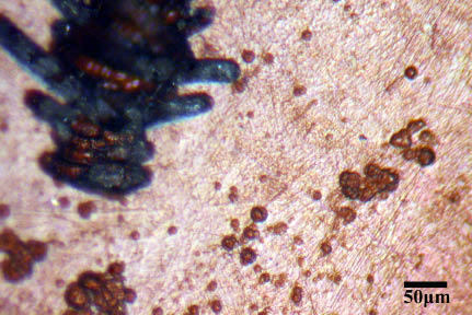
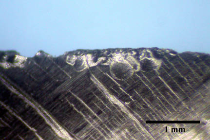
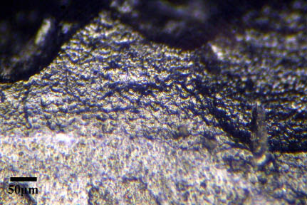
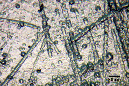
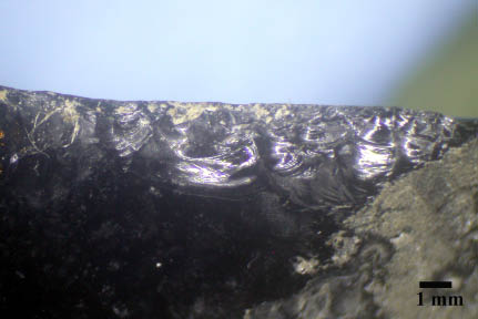
The specimen consists of a small amber glass fragment (Figure 1). The specimen is roughly square in shape and measures about 27 mm x 25 mm x 3 mm. The shard has been fractured on all edges. The four fractured edges have edge angles ranging from approximately 60-75 degrees. There is no indication of deliberate modification of the shard’s edges. By this I mean that there is no indication that the edges have been struck with a rock, ground or otherwise deliberately modified to form a particular shape or modify an edge to a particular angle. There is no obvious post-depositional surface modification caused by natural processes. However, at higher magnification there are numerous small pits to well formed vermicular features on the surface (Figure 2). The fractured edges are sharp and not rounded. There are consistent orderly deep striations across the face of the specimen. These are undoubtedly related to manufacture and can be observed in both Figure 1 and Figure 3.
 |
 |
| Figure 1. Overview of specimen 2-9-S-78. Numbers indicate areas described in text. |
Figure 2. Specimen 2-9-S-78 surface showing individual pitting as well as pits “linking up” to form vermicular features. |
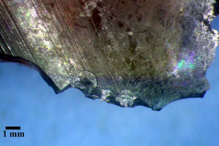 |
| Figure 3. Close up view of step and scalar fractures of Area 1. |
There are four areas that exhibit potential micro-scarring which could be attributed to secondary use. These areas are described in the next several paragraphs.
Area 1
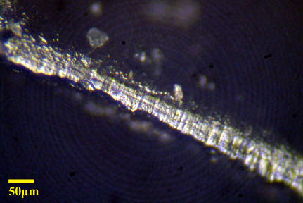
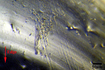
This area is the most likely candidate for modification caused by deliberate contact with another material. The edge attrition is located on side 1 (see Figure 1) upon a rather sharp projection formed from the feather termination of the lateral edge fracture. The area is 5.6 mm long and consists of about a ten primarily scalar and slight step scars ranging in length from .5 to 1.9 mm. No edge rounding was observed at either low or high power magnification. There are very few sub-transverse abrasion tracks/striations near the edge that may be the result of deliberate contact with another medium (Figure 4). Such striations or “scratches” are thought to form via some type of abrasive agent (i.e. dirt) between the tool and the item being worked (Del Bene 1979; Keeley 1974; Tringham, et al. 1974). Such scratches can be useful in determining tool motion. These tracks are not in abundance along the edge. However, there existence on other areas of the shard calls into question their relevance to any secondary use.
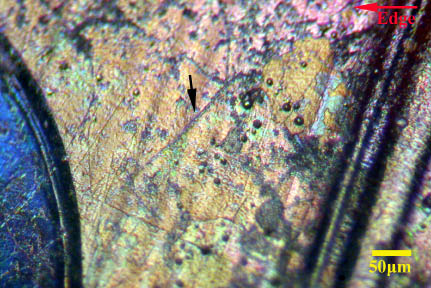
Figure 4. Highly magnified view of Area 1 showing few sub-transverse striations/scratches or abrasion tracks near the edge.
The regularized nature, small, broad size and nature of the flake scars could be indicative of brief contact with a soft to medium hard material. Figure 5 depicts an obsidian (volcanic glass) tool edge that was used to scrape fresh beech (hard) wood 15 minutes. The action resulted in the production of a number of “snap” flakes as well as patterned small scalar and step flakes depicted in Figure 5. The obsidian edge had an angle of about 35 degrees. Figure 6 is a high magnification view of the same obsidian tool edge. This view clearly depicts numerous sub-transverse striations or abrasion tracks. These striations are clear markers of the direction of tool use. These striations are similar to those observed in Area 1. In summary, it is possible that Area 1 represents a very brief contact with a material of soft to medium hardness. However, the unifacial and general sparse nature of the flake attrition also suggests that the small flake scars could have been formed as a result of some type of human or animal trampling.
 |
 |
| Figure 5. The edge of an experimental obsidian flake used to scrape beech wood for 15 minutes. Note the presence of small feather and step flakes of a size similar to those on specimen 2-9-S-78. |
Figure 6. High magnification view of the edge of an experimental obsidian flake used to scrape beech wood for 15 minutes. Note the abundant sub-transverse abrasion tracks (striations) and tiny step flake. |
Area 2
This area is located to the left of Area 1 (see Figure 1). Here a flake was detached which resulted in the medium size step fracture seen in Figure 7. The scar measures 3.7 mm wide by 2.2 mm long. This by itself is not so interesting as such a scar could have been caused by the glass being dropped or trampled. Within the same scar however, there are three or four other small step flakes indicating that the area could have been formed by a repetitive action in the same location (Figure 7). Similar interior detached step flakes can also form as the result of a percussion blow (Cotterell and Kamminga 1987:687). However, the limited nature of the attrition does not make this a strong candidate for alteration caused by deliberate use.
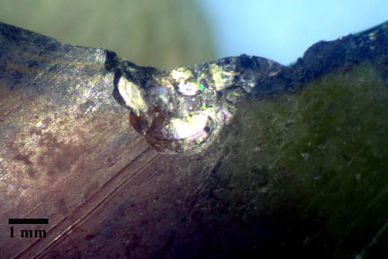
Figure 7. Area 2 consists of a medium size step flake with several other interior step flakes indicating that several small flakes were removed from a discrete area.
Area 3
Area 3 is located on side 1 along the same edge and to the left of Area 2 (see Figure 1). This area consists of a series of five scalar flakes. The largest measures 2.7 mm wide by 3.3 mm long. The other four are considerably smaller (Figure 8). The angle of the broken glass edge is fairly sharp (approximately 55 degrees). In terms of use-wear, these shallow feather flakes are generally indicative of contact with a very soft material. One possibility is that these flakes represent “prehensile wear.” I have replicated and used hundreds of stone tools and have observed that tiny scalar flakes can easily be detached in the region where pressure is applied by the fingers when grasping and using a tool. Rots (2004) has documented the formation of similar small flake scars due to prehension. Figure 9 depicts prehensile flake attrition on the non-working edge of an obsidian flake used to saw soft wood for only four minutes. Several areas of very patterned, tiny scalar flakes were formed along the edge contacted by fingers only. These scalar flakes are consistently under 1 mm in length and width and very shallow.
 |
 |
| Figure 8. Small scalar flake scars comprise Area 3. |
Figure 9. Consistent small scalar flakes from prehension on an experimental obsidian flake used to saw wood for only four minutes. Note this wear is not from sawing but from prehension only. |
If the shard was held in the hand in the manner depicted in Figure 10, in which the contact edge was Area 1, the forefinger would have been located in the region of Area 3. I believe that the contact and pressure would have been sufficient to cause the detachment of the observed scalar flakes. Alternatively, this light wear could be the result of years of being kicked around in a rocky/sandy environment.
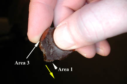
Figure 10. Possible scenario for location of small scalar flakes in Area 3. Yellow arrow indicates possible tool movement.
Area 4
Area 4 is located on side two on the edge opposite the location of Area 1-3. The area consists of eight very small scalar flake scars and one small step flake. Several of the flakes are superimposed. Most of the larger flakes are visible in Figure 11. The flake scars are less than one mm in length and width and are very shallow. As with Area 3, these scars could be indicative of contact with a soft material and are possibly prehensile in nature. The scars are very similar to the prehension caused scars on the obsidian flake depicted in Figure 9. If the tool was held in the grip depicted in Figure 10, the thumb would have likely exerted enough forward pressure on this region to cause such minute, patterned edge fracturing. The alternative scenario would again be that these fractures were caused by natural movement within the depositional environment and human and/or animal trampling.
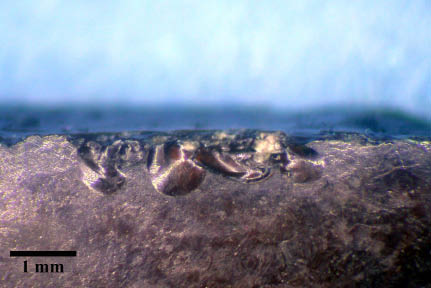
Figure 11. Very small, patterned scalar flakes in Area 4.
Summary Specimen 2-9-S-78
There are several other flake scars missing at various points along the broken edges of the shard, but no other areas that appear with numerous scars and distinct patterning as those described above. Because the edge attrition and possible use-wear on this shard is so slight, it is impossible to say with any degree of certainty that this shard represents a distinct tool of some sort. Nevertheless this specimen exhibits definite and patterned areas of distinct flake attrition. The flake attrition could very likely be a result of contact with a soft to medium hard material (such as wood) on Area 1 and possibly Area 2. The other areas represent scar patterns more indicative of very slight contact of a softer material. As demonstrated by the location of the wear patterns above and the very small size of the associated micro-flakes, the contact material could have been human fingers or a result of light trampling.
Specimen 2-6-S-16 General Description
This specimen consists of a small clear apparent glass shard (Figure 12). The shard is approximately 24 mm x 14 mm x 6.3 mm. All edges have been fractured. To the naked eye, the entire lateral edge and both faces appear to be abraded to various extents.
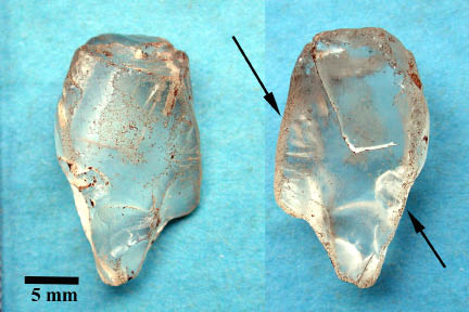
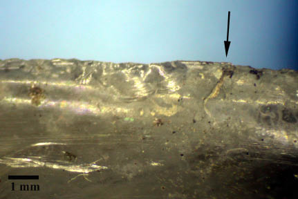
Figure 12. Overview of specimen 2-6-S-16. Arrows point to edges modified by unknown probably natural process.
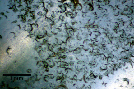
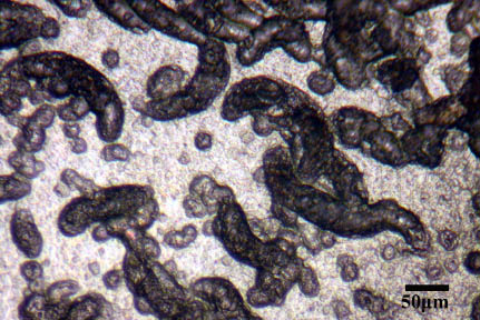
Under low power magnification it is apparent that the surface and edges have been extensively modified by either an abrasive process such as erosion caused by water and tumbling in a beach environment or a chemical process of the such proposed by Branda (1999) or some combination of both physical and chemical weathering. Figure 13 presents a low power view of the convex surface and associated vermicular surface features. There are thousands of circular, linear to semi-lunar depressions which appear to form by the linking up of circular pits on the surface. They measure approximately between 20 and 40 micrometers wide. The lengths can be considerably longer (see Figure 14). A high power view of these surface features is depicted in Figure 14.
 |
 |
| Figure 13. Low power view of features on specimen 2-6-S-16. |
Figure 14. A magnified view of vermicular features present on specimen 2-6-S-16. |
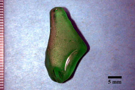
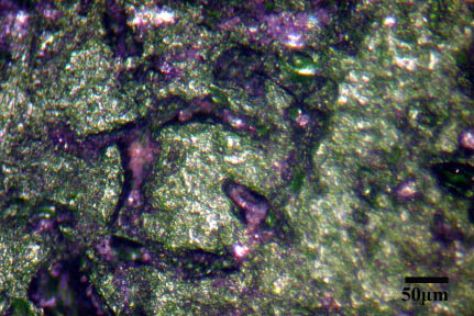
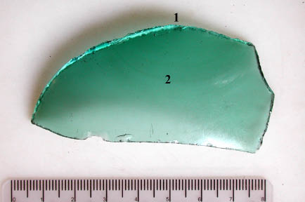
I examined the surface of a small green glass shard from what is known as “Glass Beach” near Fort Bragg in Mendocino, California. From 1949-1967 Glass Beach was a trash dump. The specimen was collected in 1997. Therefore the longest that this shard could have been exposed to the beach environment would be about 48 years. This specimen is depicted in Figure 15. The surface of the specimen has been heavily abraded and smoothed from interaction with the beach particles and water (tumbling). The edges are quite rounded. In comparison, the edges of specimen 2-6-S-16 are much more sharp and surface and edge degradation appears to be significantly less than that of the Glass Beach specimen. This may indicate that an entirely different and possibly chemical process is responsible for the surface degradation seen in specimen 2-6-S-16. A high power examination of the Glass Beach specimen reveals some depressions, but does not reveal vermicular surface features such as those upon specimen 2-6-S-16. These features are depicted in Figure 16.
 |
 |
| Figure 15. Heavily abraded/smoothed glass from “Glass Beach” in California. |
Figure 16. A highly magnified view of the California “Glass Beach” shard and the surface smoothing and depression present. |
The surface features of the Glass Beach specimen and specimen 2-6-S-16 are clearly not identical. Those on the Glass Beach specimen appear to be narrower (about 20-30 micrometers in width) and do not have the vermicular appearance. This could be explained by the fact that these two particles are being degraded by a different process. I observed no edge attrition on specimen 2-6-S-16 that could be attributed to secondary use as a tool.
Specimen 2-9-S-79 General Description
This specimen consists of a small clear apparent glass shard (Figure 17) which the TIGHAR research team has identified as a small piece from an octagon-shaped bottle. The shard is approximately 43 mm x 17 mm x 4 mm. All edges have been fractured and are fairly sharp. The edge angles vary from 65-90 degrees. Areas of both faces of the glass are highly reflective and appear to be undergoing a chemical change and formation of iridescent layering. High power magnification reveals some surface pitting and vermicular features similar, but far fewer, to those depicted in Figure 14. Upon low power magnification, it is apparent that there is substantial micro-flake attrition along certain areas of the broken edges. Unlike the previous specimen 2-6-S-16, this edge attrition is not continuous along the edge. Rather the scarring is located in discrete areas. This shard will be described by each of the faces. Face 1 is that face which forms the exterior section of the bottle. This face and the associated “areas” are depicted in Figure 17.
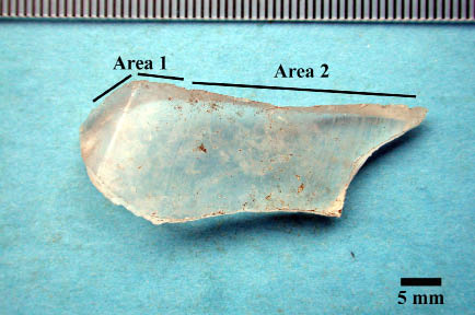
Figure 17. Specimen 2-9-S-79 face 1.
Face 1 Area 1
This area consists of consistent edge small step flakes, crushing and edge rounding. One larger step fracture is present. This larger fracture is adjacent to a recent scalar flake of about the same size. The scalar flake appears more recent and indicates that the edge attrition was formed at various times. It is not beyond possibility that the more recent scar may be a result of excavation trauma or post excavation handling.
Figure 18. Specimen 2-9-S-79 Face 1, Area 1. Note consistent edge crushing/rounding to the right. The large scalar flake to the left is of a different temporal age than the majority. However, the step flake to its right appears related to the remainder of the edge attrition.
The attrition on this edge continues around the corner towards the end of the shard. At this point the flakes are a mixture of scalar and step and are quite consistent and bifacial in nature. The flakes include several large scalar flakes (on Face 1) that appear more recent. These flakes are designated #1 on Figure 19. Area 2 appears to be an older event and consists of consistent smaller scalar flakes. Under high magnification, no striations or other indication of motion were observed. In general, the faces and edges display some “pitting” or surface degradation, but nowhere near the level of specimen 2-6-S-16.
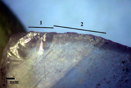
Figure 19. Specimen 2-9-S-79 Face 1, Area 1 (opposite of Figure 17). Larger apparently more recent scalar flakes to the left. Consistent smaller scalar scars to the right.
Face 1 Area 2
This edge has consistent “nibbling” and small scalar flakes. Much of this edge attrition is probably the result of natural processes. Closer to the projection, however, there are several larger scalar flakes (Figure 20). In this area the edge angle is about 55 degrees. The edge opposite “Area 1 and 2” and the “lateral” edge below the Area 2 projection both exhibit pretty consistent nibbling and occasional small scalar flakes that most likely is best associated with natural processes.
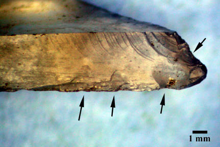
Figure 20. Specimen 2-9-S-79 Face 1, Area 2 near projection. Arrows indicate larger scalar flakes. The rest of the Area 2 edge exhibits consistent “nibbling” and occasional scalar flakes possibly a result of natural processes.
Face 2 Area 3
Face 2 is depicted in Figure 21. Area 3 consists of primarily unifacial edge attrition. The exception is less than five scalar flakes widely distributed across the edge surface depicted in Figure 21. The opposite edge face exhibits consistent small to medium size scalar flakes. Several of these flakes appear more “recent” (Figure 22). These flakes represent a very discrete area of probable contact with a soft-medium hard material. The contact was likely in a transverse to sub-transverse manner. Figure 23 depicts several very distinct sub-transverse striations.
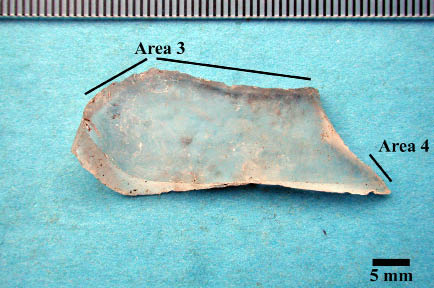
Figure 21. Specimen 2-9-S-79 face 2.
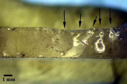
Figure 22. Specimen 2-9-S-79 Face 2, Area 3. Arrows indicate larger scalar flakes. The four flakes on the right appear more recent that the one large one on the left.
Figure 23. 2-9-S-79 Face 2, Area 3, high power magnification of sub-transverse striations at edge. Striations parallel to edge are a result of manufacture.
Face 2 Area 4
Area 4 is located near the projection (see Figure 21). The area consists of a discrete area of primarily small unifacial step flakes (Figure 24). A couple scalar flakes are also present. The area could very well represent fairly brief contact with a medium hard substance.
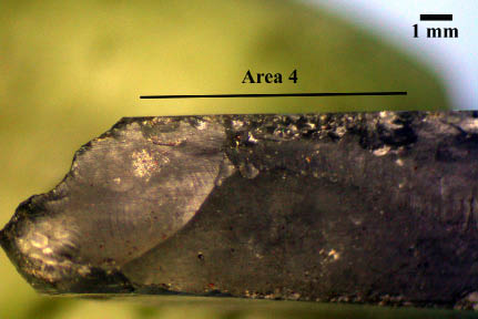
Figure 24. 2-9-S-79 Face 2, Area 4, discrete area of small step flakes.
Summary Specimen 2-9-S-79
This glass shard has at least four discrete areas of distinct flaking events. The areas appear to represent contact with soft-medium hard substances. Given the discrete patterning and bifacial nature of some locations, it is difficult to attribute these patterns to natural processes alone. The attrition patterns are primarily unifacial along the various areas. Decent evidence for sub-transverse motion is demonstrated by the striations depicted in Figure 23. For comparative purposes, Figure 25 depicts an obsidian flake edge used to scrape Yucca plant leaves (to reveal and extract fiber) for a total of 10 minutes. This action resulted in the formation of a very distinct series of small scalar and step flakes. The flakes are quite shallow and are generally between 0.2 and 1 mm in length. The attrition patters on this glass could represent primarily transverse scraping type events on materials ranging from soft plant materials as depicted in Figure 25 to a medium hard wood as depicted in Figure 5.
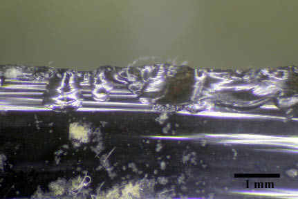
Figure 25. An experimental obsidian flake tool used to scrape soft Yucca leaves for 10 minutes. Note the abundance of shallow scalar flakes. Yucca fibers and plant residue are still firmly attached to the flake 12 years after the experiment was conducted.
Specimen 2-9-S-1b General Description
The specimen consists of one half of a larger bottle fragment (Figure 26). This piece conjoins with specimen 2-9-S1a to form what TIGHAR believes may be the top half of a of a bottle of an early 20th century product called “Freckle Ointment” (Gillespie 2011). The specimen also has iridescent layered surface weathering. High power examination of the surface reveals common small surface pits but no vermicular features. The fractured edge of the fragment forms an approximate 90 degree angle on both laterals. The distal end is more in the range of 50-55 degrees. Glass thickness is approximately six mm. There is no indication of deliberate modification of the broken edges. The surface of the glass appears to have undergone some discoloration and has attached residue. In addition, under low power microscopy it is clear that there are some pitting and surface features, similar to but not as extensive as, specimen 2-6-S-16. However, the fractured edges are quite sharp and not rounded. The interior of the fractured edge reveals only a couple instances of individual micro-flake events that are most likely from natural processes. The exterior edge has several discreet areas of consistent micro-flake attrition mainly located on the interior of the edge. These will all be described as being on the exterior face.
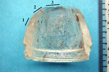
Figure 26. Overview of specimen 2-9-S-1b and areas discussed in text.
Exterior Face Area 1
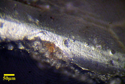
This area consists of a discrete group of about five tiny scalar flakes. The flakes are very shallow and have a length of about .7 to 1.3 mm (Figure 27). Of note is a small piece of what appears to be plant fiber adjacent to the scars and attached to the edge. Figure 28 is a slightly more magnified view of the fiber. It is difficult to say with any degree of certainty if the fiber has any direct relationship with the edge attrition. However, it must be fairly well affixed to remain on the tool edge through what has likely been pretty extensive handling. The yucca plant fibers visible in Figure 25 have remained on that experimental flake 12 years and have survived numerous episodes of handling and examination under the microscope. The environment of the lab drawer is far different from the depositional environment on the island. Nevertheless, it is possible that the fibers documented in Figure 28 could have association with secondary use of the glass.
In addition to the flake attrition, Area 1 exhibits one area directly on the edge that exhibits fairly regular striations that are transverse to the edge. However, as documented in Figure 29, the distances between the striations are highly regularized and most likely are associated with manufacture. These transverse striations correspond fairly well with very distinct striations on the face of the bottle. About 0.5 cm away from these linear features is another area of the edge which does not exhibit the striations (Figure 30). Here there are no such striations on the face of the glass. This also suggests the striations documented in Figure 29 are manufacture related and not associated with any sort of secondary use of the glass.
 |
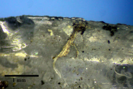 |
| Figure 27. Specimen 2-9-S-1b, Area 1, a small cluster of scalar flakes adjacent to what appears to be plant fiber (arrow). |
Figure 28. Specimen 2-9-S-1b, magnified view of probable plant fiber attached to edge in region of Area 1. |
 |
 |
| Figure 29. Specimen 2-9-S-1b, highly magnified view of Area 1 edge with fairly regularized transverse striations which are likely associated with manufacture. |
Figure 30. Specimen 2-9-S-S-1b edge just outside of Area 1 (away from bottle edge). This area does not exhibit the transverse striations as seen in Figure 28. |
Exterior Face Area 2
Area 2 exhibits several edge attrition features included very tiny edge nibbling which may be due to natural processes (Figure 31, “A”). Adjacent to the tiny edge attrition is a medium size scalar flake (Figure 31, “B”) and a medium size step flake (Figure 31, “C”). To the right of these flakes are a series of regularized striations (Figure 31, “D”). These striations are too consistent in width and spacing to be formed by secondary use. The striations also match up to a series of striations on the glass face suggesting they are in fact related to manufacture.
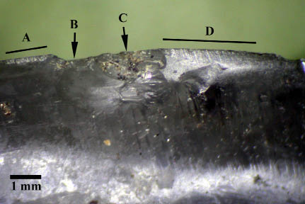
Figure 31. Specimen 2-9-S-1b, Area 2.
Exterior Face Area 3
Area 3 is adjacent to Area 2 and continues around the gently rounded corner of the fragment (see Figure 26). The fracture angle is about 60 degrees here. Along this edge are a consistent group of small unifacial scalar flakes (Figure 32, “A”). Next to this sequence is a medium size scalar flake with a number of smaller scalar flakes removed from the inside edge of the medium flake scar (Figure 32, “B”). A high power examination of the Area 3 edge yielded no evidence for linear features (Figure 33).
 |
 |
| Figure 32. Specimen 2-9-S-1b Area 3 edge attrition. |
Figure 33. Specimen 2-9-S-1b Area 3, no linear features present. Note small scalar scar to right. |
Summary Specimen 2-9-S-1b
The micro-flaking on this shard is unifacial and exists in both isolated instances as well as several somewhat discrete areas as described above. The attrition is restricted to one half of the interior edge of the bottle fragment as depicted in Figure 26. The flakes are primarily tiny to small scalar flakes. This flake pattern could have been formed by very limited transverse contact with a soft material such as plant or soft wood. There are no linear features observed that might have supported a scenario of secondary use. However, it is also possible, perhaps slightly less so, that the flaking events were entirely formed by processes such as trampling and movement within the surrounding sediments.
Specimen 2-9-S-44 General Description
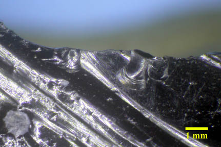
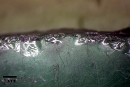
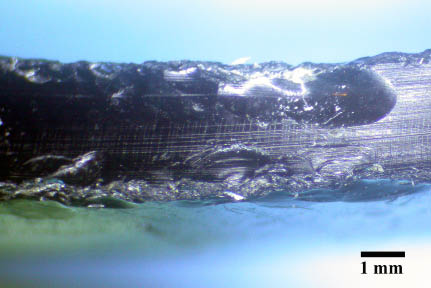
This specimen is labeled “Japanese Float Shard” and was recovered from the lagoon shore. The piece is a greenish-blue color (Figure 34) and appears to lack iridescent layering. A high power scan of the surface reveals common small pits, but few vermicular features. The piece is irregular in shape and measures 77 mm x 36mm x 1.8 mm. Extensive small to medium size flake attrition is readily apparent on all edges. A closer look reveals that the edges also have hundreds of tiny step flakes and the edge is essentially crushed and heavily abraded. (Figure 35). The faces are also covered with numerous randomly oriented fine striations (Figure 36). The piece immediately gives me the impression that it has been subjected to extensive edge abrasion and edge alteration most likely from natural forces. It would be quite odd to have this degree of edge alteration covering such a high (almost 100%) of all edges from secondary use. There are several larger flake scars which in the context of this edge are most likely attributable to natural processes or trampling. What is puzzling, however, is the fact that the glass still remains very clear and not frosted appearing from being abraded or smoothed. If the damage here was caused by tumbling, the wear on the faces seems like it may be proportionately less to that of the edges.
 |
 |
| Figure 34. Specimen 2-9-S-44, numbers indicate location of Figures 34 and 35 (#1) and 36 (#2). |
Figure 35. Specimen 2-9-S-44, intense scalar, step and edge crushing are common along the edges of the shard. |
 |
 |
| Figure 36. Specimen 2-9-S-44, overhead view of glass edge and intense edge flaking, crushing/abrasion. |
Figure 37. Specimen 2-9-S-44, abundant randomly oriented striations/abrasion tracks and linear features formed by “joining” of circular pits are abundant on both faces of the tool. |
Summary Specimen 2-9-S-44
Given the intensity and almost complete distribution of edge attrition, it is very unlikely that secondary use, if it in fact exists, can be detected and separated out from the damage caused by natural processes. In addition, to the consistent edge alteration, the numerous linear features and micro-pitting on the surface of the shard faces probably indicates that the shard has been subjected to a very dynamic environment. I suspect this wear pattern is indicative of the initial stages of rounding caused by exposure to water and tumbling action. Yet, I remain a little puzzled by the possibly disproportionate amount of wear on the faces.
Specimen 2-8-S-21b General Description
The specimen consists of a clear glass piece of an apparent octagon shaped bottle (Figure 38). The piece is irregular in shape and measures about 45 mm x 31mm x 3.7 mm thick. Macroscopic examination indicates that there is some iridescent layering of the glass. High power examination revealed some small pits and no vermicular features. The fractured edges appear sharp. The broken edge angles range from 60 to 90 degrees. Upon examination under low power microscopy, only several isolated edge scars were observed. The one exception is one of the projections.
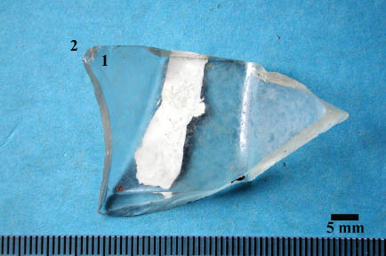
Figure 38. 2-8-S-21b Area 1 and 2.
Interior Projection Area 1
This projection exhibits portions of flake scars. This might be a fragment of a Hertzian cone from the force that caused this area of the bottle to break (Figure 39). There do not appear to be any fractures on this side of the projection formed as a result of secondary use.
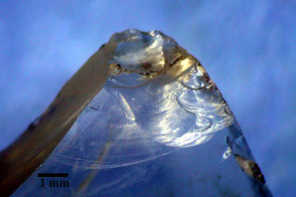
Figure 39. Specimen 2-9-S-21b, the projection displays portions of a larger fracture.
Interior Projection Area 2
This area is located on the opposite side of Area 1 and on the edge immediately adjacent to the projection. The attrition includes on medium size scalar scar on the projection (Figure 40, #1). Another medium size scalar flake is missing on the edge (Figure 40, #2). The edge displays consistent micro-scarring which appears to be more indicative of natural processes rather than secondary use (Figure 40, #3). In summary, the flake attrition on this projection is most likely related to either an impact or trampling event that snapped the shard into several pieces.
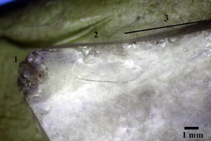
Figure 40. Specimen 2-9-S-21b Area 2.
Specimen 2-6-S-21A General Description
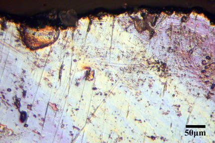
This shard has been described by TIGHAR as a possible fishing float fragment (Figure 41). The fragment is slightly discolored (purplish) and very slight layering or differential surface abrasion is apparent. Low power reveals numerous large randomly oriented surface abrasions. High power magnification reveals common small circular pits and some vermicular features. Under high power (150X) it becomes difficult to distinguish apparent abrasion related striations from those that may be forming from a chemical process. Figure 42, #1 depicts very narrow striations probably related to abrasion. Figure 42, #2 depicts a larger striation sub-transverse to the edge that could be related to secondary use. Figure 42, #3 depicts a striation that appears to be forming by “joining” of circular pits. This scenario makes it extremely difficult to distinguish which linear features represent natural processes from those that may be related to secondary use.
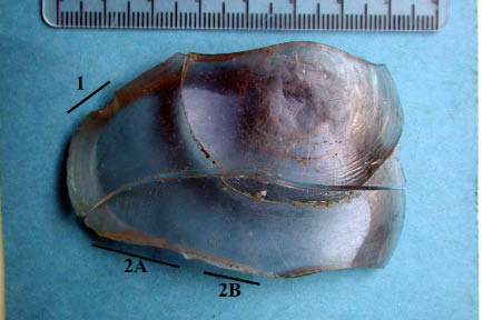
Figure 41. Specimen 2-6-S-21A overview of edge wear locations.
The specimen has been broken into two pieces. Together the specimen measures about 71 mm x 47 mm x 13 mm. The thickness varies considerably. The fractured edge varies from a sharp 35 degree angle on proximal and distal end to a dull 90 degrees on the laterals. Unlike specimen 2-9-S-44, this specimen’s edges are not completely damaged by probable post-depositional processes. Rather, there appear to be two distinct areas of unifacial edge attrition. The edge in between these regions possesses occasional minute edge scars which appear to be fairly recent and likely associated both with handling and possible trampling events.
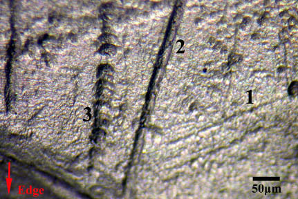
Figure 42. Specimen 2-6-S-21A linear features nearby Area 1.
Face 1 Area 1
This area represents a discrete edge area probably indicative of secondary use. The attrition is unifacial and consists of multiple small to medium size scalar flakes. The large flake to the right in Figure 43 is actually composed of at least 5 medium-large size scalar flakes. This type of wear pattern would be consistent with transverse contact with a medium hard material for a short duration of time. There are relatively large abrasion striations oriented parallel to the edge. Some of these can be observed in Figure 42. It is difficult to assign these to secondary use as there is a general background of randomly oriented abrasion striations.
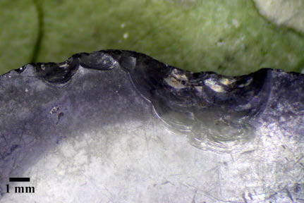
Figure 43. Specimen 2-9-S-21A, Area 1. Note the heavily abraded surface.
Face 1 Area 2A
The fracture along this edge is quite sharp as the termination “lips” out in a inflexed finial manner (Cotterell and Kamminga 1987:Figure 4). The wear is unifacial and indicative of secondary use. The thin edge has been extensively altered by flake attrition. Figure 44 depicts the region closest to where the shard comes to a point. Several large scalar flakes have been removed. In addition, the edge in this area is essentially crushed and covered by numerous small step fractures. This wear pattern is very consistent with a transverse motion contacting a hard material. Figure 45 depicts and experimental obsidian tool that was used to scrape hardwood for 45 minutes. The damage is all unifacial and the edge has essentially been crushed and contains numerous small step fractures. Under high power magnification, the obsidian experimental tool edge revealed very few sub-transverse striations (Figure 46). Those that were located clearly indicated tool motion. They were not in abundance as the tool action caused the tool edge to constantly fail. The failures (step flakes) continuously removed the striations.
 |
 |
| Figure 44. Specimen 2-9-S-21A, Area 2. Note large scalar flakes and numerous small-medium step fractures along the crushed edge. |
Figure 45. Experimental obsidian flake used to scrape hardwood for 45 minutes. Note numerous small-medium step fractures along the crushed edge. |
 |
| Figure 46. Experimental obsidian flake used to scrape hardwood for 45 minutes. Note very subtle sub-transverse striations on interior of step flake. |
Face 1 Area 2B
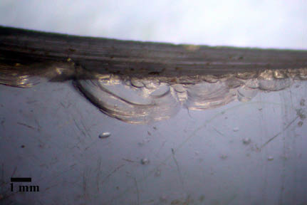
Figure 47 depicts an area about 1.5 cm away from that depicted in area 2A. The edge wear is similar. There are larger step and scalar flakes removed and then the edge has consistent small step fractures. This wear pattern is also consistent with a transverse motion against a hard material and is consistent with secondary use. The area is also consistent with the wear patterns in Area 2A.
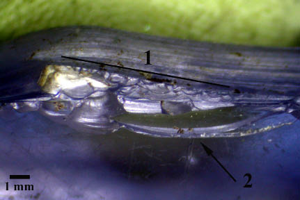
Figure 47. Specimen 2-9-S-21A, Area 2. Note very large step flake and numerous small-medium step fractures along the edge.
Summary Specimen 2-9-S-21A
This shard exhibits evidence for both natural chemical and physical surface modifications. However, both lateral edges (of conjoined piece) exhibit discrete flake attrition that is indicative of contact with a hard material in a transverse manner. This shard exhibits good evidence for deliberate secondary use.
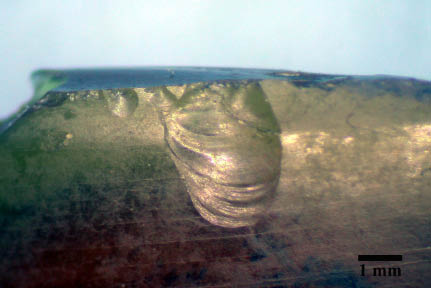
Specimen 2-9-S-1A General Description
The specimen consists of one half of a larger bottle fragment (Figure 48) that conjoins with specimen 2-9-S-1B (described above). The specimen measures 52 mm x 48 mm x 4 to 6 mm. Like its counterpart, this specimen has iridescent layered surface weathering with the same small common surface pits as seen on the other half. This specimen has the jar top. The fractured edge of the fragment forms an approximate 90 degree angle on both laterals. The fractured lateral edges are quite sharp and do not exhibit any evidence for secondary use. There is a projection at the end opposite the top of the jar. Glass thickness is approximately 5.7 mm, but is thinner at the rim. There are deep, probable, manufacture related striations on the face of the jar fragment. Both the projection and the jar rim area are of interest on this specimen. Both of these areas will be described below.
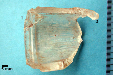
Figure 48. Specimen 2-9-S-1A, location of Area 1 and 2.
Jar Rim (Area 1– inside)
One end of the jar rim exhibits bifacial flake events. Figure 49 depicts the rim’s interior surface. There are two distinct events that have shaped the rim on the interior face. A probable percussion event caused the detachment of the large step flake. This flake is represented by the large black outline on Figure 48. The large detached flake was 17 mm long. The event that caused the removal of this large flake also caused the secondary detachment of a smaller flake. This area is outlined on Figure 49 below the yellow arrow. This type of detachment is a common result in hard hammer percussion during flintknapping (Cotterell and Kamminga 1987:687). The other smaller outline represents another distinct step flake formed from another contact episode. Given the large size of the flake that was detached, it is not likely that this flake was detached during a trampling or compression event. It is quite possible that this represents either a deliberate detachment or use of the edge of glass to tap or hit something with enough force to cause the removal of the large step flake. The blow could also be responsible for the interior fracture which is clearly visible in Figure 48 to the left of the scale bar through the face of the bottle. During examination, this area actually detached from the main piece.
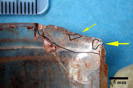
Figure 49. Specimen 2-9-S-1A, large step flake removed from jar rim. The impact point is shown by yellow arrow. The smaller arrow indicates a subsequent flake removal.
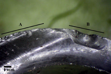
Jar Rim (Area 1 – outside)
The striking aspect of the exterior rim area of Area 1 is that there are six rather large scalar flakes removed from either use or percussion/impact (Figure 50). The removal of these flakes has formed a denticulate edge. Some of these flake ridges can be clearly seen in Figure 39. The flakes range from one to 4 mm in length and are up to 2.5 mm in width. These flakes could be indicative of transverse contact with a medium-hard material. No striations were observed at high power. However, the natural process of layer formation has altered the edge considerably and could have easily masked or removed such features.
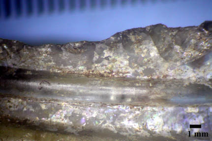
Figure 50. Specimen 2-9-S-1A, consistent scalar flakes on exterior of jar rim.
Area 2 (Projection)
Area 2 is located on the projection and consists of a small step flake (Figure 51). This attrition is so slight and limited in distribution that it most likely represents non-secondary use of the tool. This event could have easily been formed by trampling.
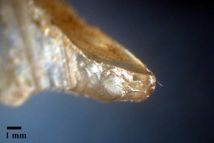
Figure 51. Area 2 (Projection), displaying small step flake.
Summary Specimen 2-9-S-1A
Most of the flake attrition in Area 1 is on this exterior side of the rim. It is hard for me to envision why someone would want to use the rather rounded rim area for a task. However, the fact remains that there is clear evidence for force loading in Area 1 on the lateral edge as well as bifacially on the area that used to be the rounded edge (see Figures 49 and 50). It is very difficult to assign this bifacial edge attrition to natural causes. However, it is also hard to understand why this edge might have been secondarily used as it originally was so rounded from manufacture.
Conclusions and Suggestions for Future Research
The purpose of this research has been to ascertain whether or not there is evidence for any secondary use on eight glass specimens from Nikumaroro Island. All of the shards examined have complex post depositional histories. All appear to be undergoing various chemical processes that are altering their physical appearance. These processes have resulted in the formation of iridescent layers, circular pitting and vermicular surface features. In addition, it is highly likely that some of the specimens have patterns of flake attrition that have resulted from trampling events. My observation is that tumbling in a beach environment is not commonly observed on these specimens. Specimen 2-9-S-44 and perhaps 2-6-S-16 were the only specimen to exhibit probable prolonged contact with an abrasive smoothing environment indicative of ocean tumbling. Table 1 summarizes the results and quantifies the certainty of assessment for the presence or absence of secondary use on the glass shards.
Table 1. Final assessment of the possibility the specimens were secondarily utilized.
I am applying a subjective five level assessment to quantify my level of confidence that a specimen was utilized. The order is as follows: (1) no use-wear, (2) poor – very few and dubious indicators for secondary use, (3) fair – not certain but fair chance that the specimen was utilized, (4) good – reasonably certain use-wear exists, (5) excellent – specimen exhibits numerous features indicative of use-wear and was certainly utilized as a tool. None of the specimens possessed enough indicators of secondary use minus abundance of post-depositional modifications for me to be absolutely certain that the observed edge modifications had been caused by secondary use.
Chemical studies may shed some light on the reasons for some of the changes observed on the antique glass. In terms of better understanding secondary use, an experimental study could be designed. In a perfect world, such a study should be conducted in the context of the substrate at Nikumaroro using glass shards of similar thickness. Trampling experiments could be conducted and several longer term experiments could be designed to monitor the effects of sunlight, wind and other variables upon the surface and edges of glass shards. Such an experiment would help to better understand the edge attrition present on these antique glass shards. I believe it also prudent to minimize handling of glass specimens excavated and collected in the future and to carefully package them in individual boxes. I believe it is possible if these shards were used for specific tasks, that residue of that action could remain. Careful packaging and limited handling of the specimens prior to examination would also limit post-excavation edge trauma. Additional research to better understand how the occupants of Nikumaroro Island post 1937 may have utilized broken glass would be quite useful.
Acknowledgments
I thank Ric Gillespie and Tom King of TIGHAR for giving me the opportunity to study these shards. I stand in awe at the terrific scientific research the TIGHAR group has been conducting under such logistical and physical difficulties that a project on an isolated island in the Pacific presents. I owe a debt of gratitude to Dr. Tom Lennon (Western Cultural Resource Management) for providing me with the introduction to the TIGHAR project. This study has benefitted from conversations with Professor Frank Hole (Yale), Professor Douglas Bamforth (University of Colorado), Mr. Jack Cresson and Dr. Charles Wheeler (Western Cultural Resource Management). Their comments have been very useful in helping me stretch my use-wear abilities to understand strictly glass specimens. However, any errors or omissions are my responsibility.
References Cited
| Akoshima, Kaoru 1987
|
| |
Microflaking Quantification. In The Human Uses of Flint and Chert, Proceedings of the Fourth International Flint Symposium Held at Brighton Polytechnic 10-15 April 1983. G.d.G. Sieveking and M.H. Newcomer, eds. Pp. 71-79. Cambridge: Cambridge University Press. |
| Bordes, François 1961 |
| |
Mousterian Cultures in France. Science 134:803-810. |
|
Branda, F., G. Laudisio, and A. Costantini 1999
|
| |
Weathering of Roman glass. A new hypothesis for pit formation on glass surfaces. Glass Technology 40(3):89-91. |
| Cotterell, Brian, and Johan Kamminga 1987
|
| |
The Formation of Flakes. American Antiquity 52:675-708. |
| Dal Bianco, B., et al. 2005
|
| |
Surface study of water influence on chemical corrosion of Roman glass. Surface Engineering 21(5/6):393-396. |
| Davis, Emma Lou 1967 |
| |
Man and Water at Pleistocene Lake Mohave. American Antiquity 32(3):345-353. |
| Del Bene, Terry A. 1979 |
| |
Once Upon a Striation: Current Models of Striation and Polish Formation. In Lithic Use-Wear Analysis. B. Hayden, ed. Pp. 167-178. New York: Academic Press. |
| Flenniken, J. Jeffrey, and J. Haggerty 1979 |
| |
Trampling as an Agent in the Formation of Edge Damage: An Experiment in Lithic Technology. Northwest Anthropological Research 13:208-214. |
| Frison, George C. 1979 |
| |
Observations on the Use of Stone Tools: Dulling of Working Edges of Some Chipped Stone Tools in Bison Butchering. In Lithic Use-wear Analysis. B. Hayden, ed. Pp. 259-268. New York: Academic Press. |
| Gifford-Gonzalez, Diane P., et al. 1985 |
| |
The Third Dimension in Site Structure: An Experiment in Trampling and Vertical Dispersal. American Antiquity 50(4):803-818. |
| Gillespie, Ric 2006 |
| |
Finding Amelia. The True Story of the Earhart Disappearance. Annapolis: Naval Institute Press. |
| Gillespie 2011 |
| |
Personal Communication. |
| Hayden, Brian, ed. 1979a |
| |
Lithic Use-Wear Analysis. New York: Academic Press. |
| — 1979b |
| |
Snap, Shatter, and Superfractures: Use-Wear of Stone Skin Scrapers. In Lithic Use-wear Analysis. B. Hayden, ed. Pp. 207-228. New York: Academic Press. |
| Juel Jensen, Helle, and Erik Brinch Peterson 1985 |
| |
A Functional Study of Lithics from Vænget Nord, A Mesolithic Site at Vedbæk, N.E. Sjælland. Journal of Danish Archaeology 4:40-51. |
| Keeley, Lawrence H. 1974 |
| |
The Methodology of Microwear Analysis: A Comment on Nance. American Antiquity 39:126-128. |
| — 1980 |
| |
Experimental Determination of Stone Tool Uses, A Microwear Analysis. Chicago: University of Chicago Press. |
| King, Thomas, et al. 2001 |
| |
Amelia Earhart’s Shoes. Lanham: AltaMira Press. |
| Levi Sala, Irene 1986 |
| |
Use Wear and Post-depositonal Surface Modification: A Word of Caution. Journal of Archaeological Science 13:229-244. |
| Lopinot, Neal H., and Jack H. Ray 2007 |
| |
Trampling Experiments in the Search for the Earliest Americans. American Antiquity 72(4):771-782. |
| McBrearty, Sally, et al. 1998 |
| |
Tools Underfoot: Human Trampling as an Agent of Lithic Artifact Edge Modification. American Antiquity 63(1):108-129. |
| Newton, R.G. 1971 |
| |
The enigma of the layered crusts on some weathered glasses, a chronological account of the investigations. Archaeometry 13(1):1-9. |
| Nielson, Axel E. 1991 |
| |
Trampling the Archaeological Record. American Antiquity 56(3):483-503. |
| Odell, George H. 1979 |
| |
A New Improved System for the Retrieval of Functional Information from Microscopic Observations of Chipped Stone Tools. In Lithic Use-Wear Analysis. B. Hayden, ed. Pp. 329-344. New York: Academic Press. |
| — 1980 |
| |
Butchering with Stone Tools: Some Experimental Results. Lithic Technology 9(2):39-47. |
| Odell, George H., and Frieda Odell-Vereecken 1980 |
| |
Verifying the Reliability of Lithic Use-Wear Determinations by “Blind Tests”: The Low Power Approach. Journal of Field Archaeology 7(1):87-120. |
| Pryor, John H. 1988 |
| |
The Effects of Human Trample Damage on Lithics: A Model of Crucial Variables. Lithic Technology 17:45-50. |
| Rots, Veerle 2004 |
| |
Prehensile Wear on Flint Tools. Lithic Technology 29(1). |
| Stapert, Dick 1976 |
| |
Some Natural Surface Modifications on Flint in the Netherlands. Palaeohistoria 18:8-41. |
| Tringham, Ruth, et al. 1974 |
| |
Experimentation in the Formation of Edge Damage: A New Approach to Lithic Analysis. Journal of Field Archaeology 1(1/2):171-196. |
| Vaughn, Patrick 1985 |
| |
Use-Wear Analysis of Flaked Stone Tools. Tucson: University of Arizona Press. |
|
Young, Donald, and Douglas B. Bamforth 1990 |
| |
On the Macroscopic Identification of Used Flakes. American Antiquity 55:403-409. |
|