 |
by Michael Everette
TIGHAR #2194
TIGHAR #2194
|
|
| A Technical Analysis of the Western Electric Radio Communications Equipment Installed on Board Lockheed Electra NR16020 | |
|
by Michael Everette TIGHAR #2194 |
| Figures |
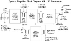
| Figure A – Simplified Block Diagram, W.E. 13C Transmitter |
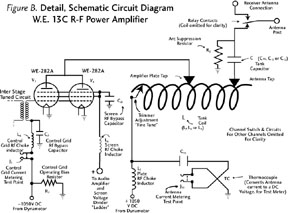
| Figure B – Detail, Schematic Circuit Diagram, W.E. 13C R-F Power Amplifier |
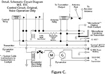
| Figure C – Detail, Schematic Circuit Diagram, W.E. 13C, Control Circuit, Original; Voice Operation Only |
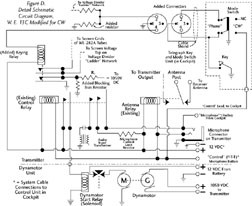
| Figure D – Detail, Schematic Circuit Diagram, W.E. 13C, Modified for CW |
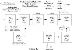
| Figure 1 – Western Electric Model 20B Radio Receiver, Block Circuit Diagram |
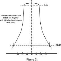
| Figure 2 – Frequency Response Curve, 96KHz 1-F Amplifier |
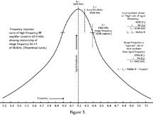
| Figure 3 – Frequency Response Curve, HF RF Amp Tuned to 6210 KHz |
| Schematics |
| Schematic 1 – Western Electric 13C Transmitter, Original Design. |
| Schematic 2 – Modified 13C Transmitter |
| Schematic 3 – Western Electric 13C Schematic, Modified for CW and 500 KHz Operation |
| Schematic 4 – Western Electric Model 20B/20A Receiver, Wwith 27A Control Unit. |
|
| Introduction | |||||||||||
|
During the 1930s, radio technology experienced a highly developmental Golden Age paralleling that of aviation. New ideas, new methods and new manufacturers emerged. Change was constant, much like computer technology in the current era. The radio communications equipment chosen by Amelia Earhart for the Lockheed Model 10E Electra, registration NR16020, which she planned to fly around the world in 1937 was designed and built by Western Electric Company, the manufacturing arm of the American Telephone and Telegraph Company. AT&T had been involved in radio communications and broadcasting since the dawn of the art, and owned many basic radio patents. Western Electric, and Bell Telephone Laboratories, were leaders in the field. Earhart’s aircraft was dubbed a flying laboratory, but its radio equipment was hardly on the cutting edge of technology. By the time of Earhart’s epic flight, the design of the equipment was more than three years old. The transmitter and receiver had been developed originally for the growing commercial airline market, and first appeared in the marketplace in 1935. The equipment was average for the time: a basic, no-frills design. It was proven reliable in airline service; but compared to the magnitude of Earhart’s proposed flight, airline operations and airline communications requirements were very minimal. This study examines the technical details of the equipment’s design and operation. It is hoped that through this information, new appreciation and insight may be gained regarding the communications problems and potential difficulties faced by Amelia Earhart in her 1937 round-the-world attempt, and perhaps understand how these may have contributed to her disappearance. The ultimate technical research source would, of course, be the Handbooks of Maintenance Instructions for the Western Electric Model 13-series transmitters and 20-series receivers. Copies of these, unfortunately, could not be found; but two excellent period books provided schematic circuit diagrams, installation information, tuning procedures for the transmitter, and some servicing information for the transmitter and receiver. These are: Modern Aircraft Radio, by Willis L. Nye, Aviation Press, 1937; and Aircraft Radio and Electrical Equipment, by Howard K. Morgan, Pitman, 1939. General information regarding 1930s transmitter, receiver and antenna design and operation, test procedures, etc., is found in numerous technical publications from the period. An excellent source is the Radio Amateur’s Handbook, annually published by the American Radio Relay League, Hartford, Connecticut. Aircraft radio communications equipment of the 1930s, especially that used in commercial service, was very unsophisticated. Its design, construction and circuitry were only just beginning to journey down the road of increasing specialization. In 1937, the chief differences from other apparatus of the era were mechanical, pertaining to remote-control operation; and in packaging. Primary sources dealing with conditions aboard NR16020 include reports written by an official of Guinea Airways, and a government administrator for general aviation in New Guinea, following Earhart’s disappearance. Another valuable source is the later recollections of a technician who worked on the NR16020 radio installation in Burbank, California, prior to the second world flight attempt. An unpublished research report compiled by TIGHAR, titled “NR16020: An Analytical View,” contains many photographs illustrating the interior of the aircraft, including views of some of the communications equipment, at various times; as well as detail drawings of the antenna system. These sources, and others, are described in the Bibliography. The original schematic drawings and diagrams of the equipment are very difficult to read and impossible to reproduce with any accuracy due to the layers of degradation suffered in the photocopying and enlarging process. For this reason, very careful computer copies of each relevant drawing have been made. Every effort has been made to insure accuracy in transcription; please bring any errors to the attention of the editors. The Western Electric Model 13C Transmitter The Western Electric Model 13C radio transmitter was a fifty-watt output, crystal-controlled unit. The original design of this transmitter produced amplitude-modulated (A-M) voice (A3 emission) signals only. The transmitter aboard NR16020 was factory-modified to incorporate Morse code (C-W) transmission capability (A1 emission) as well. Model 13C was the factory designation for a three-frequency transmitter operating in the 2500-6500 KHz range. A 1939 source (Morgan) illustrates a Model 13CB, a three-frequency radio with C-W and low-frequency (325-500 KHz) capability. Earhart’s Model 13C was factory-modified to include 500 KHz operation, and was probably the prototype for this later off-the-shelf version. The circuit consisted of three radio-frequency stages: a crystal-controlled oscillator using one Type WE-205D triode tube, a frequency multiplier/buffer stage using a single WE-282A pentode tube; and a power amplifier with two WE-282A tubes operated in parallel. The crystal oscillator operated at one-half the transmitting frequency on the high-frequency channels; on the low frequencies, no multiplication was used. For voice operation, a single audio stage using a WE-205D tube provided screen-grid modulation of the power amplifier (final amplifier) stage.
The WE-282A was a low-amplification-factor tube, requiring a relatively high level of excitation, or drive power from the preceding stage in order to achieve maximum power output. The single 282A buffer/multiplier operated at a power level almost half that of the final amplifier stage. The crystal oscillator operated at a high power level as well, 15 or more watts. A schematic diagram in Morgan's 1939 book shows a design change in the transmitter, replacing the WE-205D oscillator and audio tubes with Type 6L6 beam-power tetrode tubes. The 6L6 was a far more modern and efficient tube than the relatively soft (low-transconductance) 205D, resulting in more reliable oscillator operation and providing increased drive to the buffer/multiplier stage. Using the 6L6 provided somewhat more audio power for modulation. It is not known whether the transmitter aboard NR16020 at the time of the second world flight attempt incorporated these circuit changes. (NOTE: The diagram in Morgan also shows a modification for five channels rather than three, and is credited “Courtesy American Airlines” rather than Western Electric. The 6L6 modifications may have been part of a program carried out by the airline in its own shops, rather than by the manufacturer.) The final amplifier operated at a power input of approximately 110 watts to produce 50 watts average modulated output on voice. The transmitter operated from the 12-volt DC electrical system aboard the aircraft. The tube filaments and the relays in the control circuitry were powered directly from 12 volts. High-voltage power for the tubes was provided by a dynamotor, a motor-generator unit which operated from the 12-volt system and produced 1050 volts DC at approximately 300 milliamperes. Primary power requirements for the transmitter were approximately 11 amperes on standby (tube filaments alone), and 65 amperes on transmit using voice (tube filaments, relays, and dynamotor). The tube filaments were energized continuously in standby mode; instant-heat tube technology had yet to be developed. The dynamotor operated, in voice mode, when the press-to-talk circuit was activated using the microphone button. When the transmitter was switched to C-W mode, the dynamotor ran continuously. Control circuit details will be addressed later. The transmitter weighed 50 pounds with all coils and crystals installed, exclusive of the dynamotor unit and remote control head. Radio Frequency Circuitry and Tuning The 13C was originally designed to operate in the high-frequency (H-F) range of 2000-6500 kilohertz (KHz), on three independent channels. Each channel employed its own frequency-control crystal, and tuned circuitry in all three radio-frequency stages. Channel shifting was accomplished by means of a multi-gang switch to select crystals and tuned circuits for each channel. The switch was activated from a crank on a remote control head located in the cockpit, linked to the transmitter through a flexible tach-shaft resembling an automotive speedometer cable. All tuning adjustments were inside the transmitter cabinet and were set by a technician prior to flight. No operator-adjustable tuning controls were employed. No meters were incorporated for monitoring operating parameters, as a test set with a plug-in meter was used for this purpose while tuning the equipment. The transmitter had nine individual test points for measuring audio amplifier plate current, oscillator control grid and plate current, buffer/multiplier control grid and plate current, final amplifier control grid, screen grid and plate current, and antenna current. These parameters could only be monitored one at a time, as the single meter on the test set had to be plugged into each point. Two H-F channels were installed: 3105 and 6210 KHz. The equipment was factory modified to include capability to operate on one low-frequency (L-F) channel, 500 KHz. In 1937, this was the international distress frequency, employed aboard ships since the early days of radio and consequently adopted for aircraft. The L-F channel took the place of one of the three H-F channels. The 13-series transmitters required the installation of one of several final-amplifier tuning coils and corresponding values of fixed capacitors to cover the specified frequency range. These elements make up the final tank circuit. In technical terms, coils (inductors) are referred to as L and capacitors as C elements. In any transmitter, optimum efficiency is obtained when the L/C ratio (inductance to capacitance) is ideal to match the operating conditions of the amplifier tubes to the antenna, or load. Specifications detailing the inductance values (measured in microhenries) and physical dimensions (diameter, wire size, numbers of turns) for the coils are not available; but the H-F range was covered as follows: 2000-3000 KHz used a WE-7C coil with a 4000 picofarad capacitor; 3000-4000 KHz, WE-7B coil and 4000 picofarad capacitor; 4000-5000 KHz, WE-7B coil and 250 picofarad capacitor; 5000-6000 KHz, WE-7A coil and 250 picofarad capacitor; 6000-6500 KHz, WE-7A coil and 125 picofarad capacitor. A note in the tuning procedure specifies that occasionally it would be necessary to substitute a 62.5-picofarad capacitor for the other specified values of fixed capacitors, if the normal values did not give satisfactory operation. The above circuit values are those employed when the transmitter was operated into a more-or-less standard type of aircraft antenna, a nonresonant length of wire which varied widely in characteristic impedance with respect to frequency; with the feed connection between antenna and transmitter being a single, open wire. No information is available concerning the tank-circuit values used for L-F operation at 500 KHz. The 13-series transmitters were tuned by positioning taps on the output tank coil. Most transmitters of the period employed variable capacitors, with a untapped fixed coil, to tune the final amplifier; but in the 13-series, all capacitors in the final tank circuit were of the fixed type. The tank circuit was a crude arrangement even by mid-1930s standards. It was a series-tuned circuit. A single inductor was used, with two taps: one to connect the output-tube plates to the optimum point on the coil; and a second to connect the fixed capacitor (in series with the antenna) to the coil. A trimmer adjustment, consisting of a screwdriver-adjusted roller-type tap which moved over a limited range at the very end of the coil, was used to fine-tune the antenna after the proper tap was located. Tuning by changing coil taps, and with only a single test meter, makes for a cumbersome and time-consuming procedure. The taps must be moved between coil turns one at a time, the final-amplifier plate current and antenna current indications checked for resonance, the taps moved again, etc. until proper tuning is achieved. Changing the antenna tap causes a reaction in the amplifier tuning, and vice versa. It also means that the manufacturer’s recommendations must be closely adhered to, as the transmitter is not very versatile in its ability to accommodate variation in the installation and operating conditions. This is especially true with regard to antennas. The tuning procedures for the 13-series transmitters are quite specific concerning antennas. In the high-frequency range, using single-wire-feed and no antenna tuning unit, a length of 40 feet, nose to tail, is called for; in other words, a straight wire. The L and C values in the final tank circuit were chosen with this in mind. The matter of low-frequency antennas will be discussed later. If the proper length of antenna wire was employed, the taps on the transmitter tank coils should be capable of correct adjustment to properly couple, or match, the radio-frequency (R-F) signal output to that antenna on any frequency within the H-F operating range. It was important to place the coil taps so as to use the correct amount of turns on the tank coil, thereby maintaining the correct L/C ratio in the final tank circuit. If the antenna length was changed, it would be possible to compensate for this by placing the taps on another point on the coil and still achieve resonance in the tuning. R-F energy would still be coupled into the antenna; but the L/C ratio of the tank circuit might not be optimum. In that case, the efficiency would suffer, and the amount of R-F output would be reduced. Proper tuning is critical in a transmitter employing screen-grid modulation. To achieve optimum power output under conditions where the operating efficiency is varied – as happens with this form of modulation, because the voltage applied to the screen grids of the output tubes varies with audio supplied from the speech amplifier stage, and as screen voltage and current increase, output power increases – the tubes must be working on a precise point on their characteristic curve. This is a graph, unique to each type of tube, which shows the relationship of the operating parameters of the tube: plate voltage and current, and screen grid voltage and current, with respect to control-grid bias voltage. The tuning procedure is also quite specific regarding the setting of the idling value of screen current, i.e., under an unmodulated (no voice signal applied) condition; as well as proper placement of the tank-coil taps to achieve an upward swing of the value of antenna current when speaking into the microphone. When the transmitter was properly matched to the antenna, the test-set meter plugged into the antenna-current test position would show an upward swing of approximately 20% in antenna current on voice peaks. If the L/C ratio of the final tank was not correct, therefore, the transmitter power output to the antenna would suffer. It is not really practical to expect that a given amount of antenna current is any reliable indication of exact power in watts. Antenna current readings vary widely with the same transmitter, operating on different frequencies, into the same length of antenna. The readings are, therefore, only a relative indication of output. The characteristic impedance (a complex concept, perhaps best understood if we call it the radiation resistance or load resistance) of a given length of wire varies widely with respect to frequency; therefore the indication of antenna current will also vary widely with frequency. In accordance with Ohm’s Law, if the impedance is low, the current indication for a given power output will be high; conversely if the impedance is high, the current indication for the same amount of power will be low. In aircraft work, the actual impedance of an antenna is often difficult to determine. It was common practice, during the 1930s and 1940s, to “tune for maximum smoke;” that is, for maximum indication on the antenna-current meter, regardless of the actual reading. The radio technician primarily observed this parameter when tuning the output; for, if you had amps in the antenna, you were getting power out and that is what mattered. The only problem with this method was that it could be very deceiving; especially if some characteristics of the antenna were not well understood, which was common among technicians who were hands-on types rather than having an engineering background. Tuning procedures for the Model 13C had been worked out by laboratory engineers, and established under exact conditions. Those engineers would have had knowledge of the antenna characteristics far beyond that of the average radio technician. These procedures had been simplified for the technician’s use. Under somewhat specific conditions, the transmitter would be tuned thus-and-so, and would perform in a specific way. Many technicians had empirical knowledge in those days, and often disdained engineers because the technicians often had gotten results through nonspecified means under conditions differing from those in the lab, which encouraged them to believe they knew better. Sometimes the technicians were right. Other times they were sadly mistaken. Audio Circuitry and Voice Modulation The Model 13C transmitter employed screen-grid modulation of the power amplifier stage. This is a form of low-level modulation in which audio voltage is coupled to the amplifier tube screen grids through a transformer, after being amplified in an audio power stage. The single audio amplifier stage in this transmitter was driven by audio from a carbon-type microphone, transformer-coupled to the audio tube control grid. Screen modulation is an inherently less efficient method of modulation than high-level modulation of the final amplifier plates. Screen modulation, however, requires less weight by eliminating the need for a high-power audio amplifier and the heavy modulation transformer associated with it; less power is required to operate the transmitter because a high-level plate-modulator stage would consume almost as much current as the R-F amplifier. On the down side, screen modulation does not permit high modulation levels of the R-F amplifier – a theoretical upper limit of 90%, as opposed to 100% with plate modulation. A screen-modulated transmitter must be more precisely tuned, also. The audio circuitry of the 13-series was simple, but normal for the era in which it was designed. There were no automatic gain features or compression amplifiers to boost the average audio level from the microphone. Actual experiments conducted by this writer with other aircraft transmitters of generally similar overall design, from roughly the same era, shed light upon the operational capabilities of the 13C. These experiments were performed with an SCR-274N equipment, a system designed in the mid-1930s originally for the U.S. Navy by Aircraft Radio Corporation of Boonton, New Jersey; and later adopted by the U.S. Army Air Corps. A similar experiment used a U.S. Navy Model GF-12 transmitter, a unit manufactured by Western Electric and of somewhat earlier design than the 274N. Both radios were widely used during World War II. The 274N uses a pair of Type 1625 tubes in the power-amplifier stage, screen-modulated by a single 1625. The GF-12 uses a pair of Type 837 tubes, suppressor-grid modulated by a single Type 89. (Suppressor-grid modulation is another method of low-level modulation, closely comparable to screen modulation.) The radios were bench-tested in exactly the configuration used when installed in aircraft, operating from their dynamotor power supplies, using a DC power source (28 volts). Standard handheld carbon microphones as used in aircraft were employed: Signal Corps Type T-17 for the 274N and Navy Type RS-38A for the GF-12. An audio signal generator was also used to inject a tone for more precise tests. Modulation waveforms were observed on an oscilloscope. Actual peak modulation levels in these equipments under ideal conditions, with tone input from the audio signal generator, reached about 80%. Speech input from the handheld carbon microphone produced around 75% modulation. Signals from these transmitters heard by a receiving operator would seem to have low, mushy audio level, compared to the punch of a fully-modulated (100%) signal. The lower level of modulation would be a further disadvantage if the received signal strength was weak, because of a lower ratio of signal to noise at the receiver. A low-level-modulated voice transmission in the noise would be even more difficult to understand. Additionally, the audio fidelity was poor, mainly due to the microphones employed. Carbon microphones of the 1930s and 40s were very similar in design and construction to a telephone-type microphone element. These microphones had to be close-talked; that is, held up almost directly in front of the lips. They were not noise-canceling, so any background noise from the aircraft engines and propellers was also picked up, further reducing intelligibility. It was necessary to speak slowly and deliberately, usually with a raised voice, to make oneself understood. The Transmitting Antennas Aboard NR16020 The high-frequency antenna installed aboard the Electra in March 1937 was a “Vee” type running from the tip of each of the twin vertical stabilizers to a mast atop the fuselage, located at Station 176. The antenna was, therefore, a total of 46 feet, doubled back onto itself. This length did not include the lead-in wire which exited the aft fuselage through a feed-through insulator and connected to one leg of the Vee at a point a few feet from one of the vertical stabilizers. This antenna was, then, already 15% longer than optimum; but since the radio equipment had been installed by Bell Labs, it can be fairly assumed that it was tuned properly at that time. The length of 46 feet was greater than 1/8 wavelength at 3105 KHz (approximately 38 feet) and greater than 1/4 wavelength at 6210 KHz (again, approximately 38 feet; this relationship is due to the fact that 6210 KHz is the exact second harmonic of 3105 and the wavelength at the higher frequency is half that of the lower); or, a non-resonant length at either frequency. This antenna was unsuitable for low-frequency 500 KHz operation, as the total length would be miniscule compared to the wavelength at this frequency. The wavelength of 3105 KHz is about 97 meters (315 feet), and about 48.5 meters (156 feet) at 6210. At 500 KHz, the wavelength is 600 meters (1950 feet). For 500 KHz, a second antenna was originally employed. This antenna was the trailing-wire type. The antenna was reeled out from the belly of the aircraft and had a full length of 250 feet. This was still shorter than a resonant length at 500 KHz, but a much larger relative component of the wavelength than the 46-foot Vee. With the addition of a special loading coil, mounted inside the fuselage near the transmitter, connected in series with the antenna to electrically lengthen it, the trailing wire could be effectively matched to the transmitter. The trailing wire’s disadvantage was that it had to be reeled out after takeoff and in before landing. A manual switch was also needed to transfer the transmitter output from the H-F Vee to the L-F trailing wire. This switch, necessarily, was located close to the transmitter which was mounted in the aft section of the fuselage next to the navigator's table. Since the fuselage was almost filled with huge fuel tanks between the navigator’s station and the cockpit, it was very awkward to change antennas if the navigator was riding up front. After Earhart’s first round-the-world flight attempt in March 1937 ended in a takeoff accident at Luke Field, Hawaii, NR16020 was rebuilt by Lockheed. Earhart, obsessed with saving weight, also wanted to simplify the radio operation. She desired to remove the trailing wire, undoubtedly not fully appreciating the significance of and requirement for its long length for successful L-F operation. Joseph Gurr, a radio technician privately engaged by Lockheed to check out the communications equipment while the aircraft was under repair at the Burbank factory, proposed that if the fixed H-F Vee antenna could be lengthened, it would serve on both 500 KHz and the high-frequency channels. He moved the antenna mast on the fuselage forward from Station 176 to Station 129.5, increasing the Vee’s total length to 54 feet. There was a further slight increase in the length of lead-in, because the location of the feed-through insulator was changed to a point lower on the fuselage side. The antenna was now almost 33% longer than the optimum length specified for the 13 series transmitter, in the H-F range. As for 500 KHz, this extra eight feet made practically no difference. At H-F, however, the extra length radically altered the tuning. The length of antenna plus extra lead-in was now very close to an odd fraction of a resonant length on both frequencies, 3/16 wavelength at 3105 and 3/8 wavelength at 6210 (about 57 feet in each case). The increase in length meant a radical change in the antenna’s characteristic impedance at both frequencies. Complete retuning of the transmitter was necessary, and this spelled trouble. With increased antenna length, the conditions of the tuning procedure were violated. Unless changes were made in the transmitter to maintain the proper L/C ratio in the final tank – specifically, to change the values of the capacitors in the circuit – tuning for maximum smoke would be deceptive. In actual practice, these odd fractions of a resonant wavelength are often difficult to properly match. The reason for such difficulties lies in the R-F voltage and current distributions over the length of the antenna wire, and resultant standing waves along the antenna. This is particularly true of an antenna 3/4 wavelength long, as this one was at 6210. It is conceivable that a technician attempting to compensate for changes in antenna length might have installed a tank coil with a different number of turns, and consequently different inductance, from the one specified for a particular frequency range; for instance, a 7B coil for 6210 KHz rather than a 7A. Without making other changes in regard to the fixed capacitors – changes the technician may not have been entirely qualified to judge – the results may have been even more confusing. Another potential compounding of the antenna problem may have resulted from the Vee configuration of the dorsal antenna. The doubling-back of the antenna length in the Vee configuration could have played havoc with the antenna’s characteristic impedance, as the two halves of the Vee may have reacted upon each other. Also, a Vee configuration meant that more of the antenna was in close proximity to the metal skin of the aircraft, which could have further affected its operation and tuning. If the antenna is in close proximity to the metal skin, which is at ground potential, the antenna’s capacitance to ground is increased, resulting in a lowering of the actual resonant frequency. The transmitter could easily have become so mistuned that power was actually being radiated on the wrong frequencies. The 13C employed frequency multiplication in the H-F range to effect greater frequency stability, avoiding feedback from the final to the oscillator. It also minimized carrier shift, or pulling, a form of instability occurring when the varying voltages in a power-amplifier stage under modulation cause a corresponding reaction in the voltages on the oscillator stage, causing the frequency to vary slightly (this can be a problem even with crystal control). The result is a voice signal which is broad, spreading out over too much bandwidth. If the final tank L/C ratio was not optimized, it might be possible for the third harmonic of the crystal to be amplified, rather than the second. This would be more likely to happen on the higher H-F channel, 6210 KHz. Power output on the desired frequency would be much reduced; but a technician tuning for maximum amps in the antenna might be fooled if power produced on the wrong harmonic gave a greater indication of antenna current than should be expected on the correct frequency. If the transmitter were mistuned, the modulation quality would suffer. The signal might become broad and the speech distorted. Indeed, observations were made at Lae, New Guinea, before Earhart’s final takeoff which indicated such distortion on 6210 KHz (see Chater). Again, however, we must assume that the transmitter was properly tuned when the aircraft initially left Bell Labs, before Gurr modified the antenna. It would be interesting to know how much deviation from standard tuning procedure may have been taken by their engineers, but available records do not reveal this. How the Problems Could Have Been Solved An alternative installation of the Model 13-series transmitters is outlined in the technical information and tuning procedures contained in Morgan. This alternative employed a far superior method of coupling the transmitter to the antenna which, had it been incorporated aboard NR16020, would have minimized or eliminated many of the problems on the H-F channels. Rather than directly connecting the transmitter to the antenna with an open-wire feed, a 70-ohm coaxial-cable transmission line was specified; but the coaxial line was not connected directly to the antenna. A separate antenna tuning unit would be used to match the antenna’s characteristic impedance, which varied widely with frequency, to the 70-ohm line. The tuning unit consisted of an additional tuned circuit serving as a matching network or radio-frequency transformer. This circuitry would also provide much-needed isolation between the antenna and the transmitter tank circuit, resulting in suppression of harmonic radiation. Component values specified for the transmitter tank circuit would be somewhat different when working into the low-impedance coaxial line. In the 2000-3500 KHz range, a 250-picofarad capacitor and WE-7B coil were used; for 3500-6500 KHz, a 250-picofarad capacitor and a 7A coil. In addition, a 1000-picofarad loading capacitor would be required, connected between the transmitter antenna post and ground. Morgan does not contain circuit details or diagrams of a tuning unit, or a mechanical description to show if the device could be remotely controlled. Logic suggests that for such a unit to be operationally compatible with the transmitter, it would contain individual switch-selected tuned circuits for each H-F channel, selected by remote control. A separate remote-control head may have been required for the purpose; or the unit may have been mechanically coupled to the same control head and tach-shaft that operated the channel-shifting switch in the transmitter. If the antenna tuning unit was not remotely controlled, it would have to be manually adjusted for each channel by a radio operator. Whether an antenna tuning unit was available as an optional accessory from Western Electric, or whether such may have only become available subsequent to the 1937 Earhart flight is not known. Morgan does not describe any manufacturer’s tuning unit, or give type numbers. It must be noted, however, that there is no evidence that Earhart’s installation incorporated an antenna tuning unit. Photos of the cockpit of NR16020 do not show a separate control head which might be associated with an antenna tuning unit. The unit itself would have to be installed very close to the point where the antenna feeder wire entered the fuselage through a porcelain insulator. Such a device does not show up in photos of the interior of NR16020. Beyond the lack of photographic evidence, there is no mention of an antenna tuning unit in the writings of Joseph Gurr. Amelia Earhart’s obsession with saving weight may well have been a factor. The tuning unit would likely weigh at least half as much as the transmitter itself. If the radio system could be made to operate without the extra 25 or more pounds of weight, Earhart would likely have opted not to include it. Had a tuning unit been employed, the possibility for transmitter mistuning and resultant harmonic radiation would have been greatly reduced. Such a device would offer a far greater range for properly matching the antenna, despite its proclivities, to the transmitter output; yet, high standing waves on a 3/16- or 3/8-wavelength wire would have made tuning this antenna, at either 3105 or 6210, a formidable task using antenna current readings alone. (The VSWR bridge, a test instrument which measures standing-wave ratio and gives an indication in terms of a null on a meter, when a low-impedance transmission line such as 70 ohms is properly matched to an antenna through a tuning unit, did not come into general use until the late 1940s.) The high-frequency antenna tuning unit was a device entirely separate and different from the loading coil required for operation on the low-frequency 500 KHz channel. The frequency of 500 KHz was essential for the round-the-world flight. Until the middle of World War II, this was the only universally monitored (guarded) distress frequency. Ships at sea, and maritime shore stations, were required by international regulations to maintain watch on 500 KHz. During specified parts of every hour, radio silence would be observed in order to listen for stations in distress. At all other times, 500 KHz was a calling frequency. Ships, shore stations and aircraft made initial contact on 500, then moved to other working frequencies like 410 or 425 KHz. The 13 series transmitter could provide voice or C-W output on 500 KHz. The frequency, however, was almost exclusively used for C-W operation by all stations guarding it. Indeed, a weak voice transmission would likely have been dismissed by anyone hearing it as some form of interference. Originally, NR16020’s crew was to consist of Earhart as pilot and Harry Manning as navigator. Manning was also an experienced radio operator. Manning, however, backed out of the flight prior to the first attempt; and Fred Noonan became the new navigator. Neither Noonan nor Earhart could be classified as a radio operator (see Chater and Collopy for corroboration). Neither had sufficient Morse proficiency to seriously consider using C-W, even though under most conditions Morse transmissions will carry much further than A-M modulated voice – a consideration which should have been valued in a potential emergency. Earhart, whose knowledge of and patience with radio was limited at best, determined to get rid of the trailing wire since Manning was no longer there to operate it. At first this seemed to entirely eliminate the 500 KHz capability – until Joseph Gurr entered the picture. Gurr offered to increase the length of the Vee, and make it work on 500 KHz. To do so, he removed the Western Electric loading coil used with the trailing wire – a relatively small value of inductance – and substituted a very large, home-made coil. The extra antenna wire did not bring the antenna any closer to a proper length for low-frequency operation; but it may have been just enough, judging by an antenna-current indication alone, to make things appear to be working on 500 KHz. This was a serious mistake. For the most part, the transmitter’s output power was being dissipated in the coil, rather than radiated by the antenna. Very little R-F was actually going out despite whatever antenna current reading may have been observed. Any signal radiated by this system on 500 KHz would be extremely weak. To overcome the losses in the loading coil and achieve any meaningful signal output would have required tremendous transmitter power in order to afford being able to waste a lot of R-F – far greater power than the 50 watts produced by the 13 series transmitter. It is not known for certain whether Gurr’s modifications included the removal of the antenna transfer switch as well. One function of this switch was to remove the loading coil from the antenna circuit on H-F. If the huge homemade coil was left in the circuit all the time, operation on 3105 and 6210 could have been even more affected. The coil could have acted like a radio-frequency choke, blocking part of the transmitted power as well as part of the received signal. The Modifications for C-W Operation C-W is, literally, the abbreviation for “continuous wave.” In common usage and practice, C-W designates radiotelegraphy transmission using an unmodulated R-F carrier wave, turned on and off with a telegraph key to form the dits and dahs of Morse code. The 13-series transmitters were originally designed for voice operation only. The one aboard NR16020 was modified for C-W operation, primarily because of the requirement to operate on 500 KHz. This involved two major changes: alteration to the control circuitry; and the addition of a keying relay. The dynamotor was operating only when the control circuit was closed (grounded) by the microphone push-to-talk button, and the transmitter was actually delivering a signal on the air. Such an arrangement is not suitable for C-W operation. On C-W, the high-voltage supply to the transmitter tubes must remain ready at all times, even when the telegraph key is up. The keying speed of radiotelegraph transmission is too fast to allow for a dynamotor to start and speed up between dits and dahs of Morse characters. In the original 13C control circuit, if the transmitter push-to-talk circuit was activated by closing a telegraph key instead of the microphone button, the dynamotor starter relay would be switched on and off each time the key was operated. This relay would be very large, similar to an automotive starter solenoid, and not mechanically capable of following a telegraph key. The high current drawn by the motor generator – about 53 amperes, with start surges of well over 100 amperes until the inertia of the machine is overcome – would quickly destroy the starter relay contacts due to arcing as the circuit opened and closed. Also, the voltage output of a dynamotor varies with its speed of rotation. If the machine tried to follow a telegraph key, the wild voltage fluctuations caused by its constant starting, speeding up and slowing down would produce an unacceptably unstable, poor quality signal with a wild yoop or chirp characteristic. Aircraft transmitters initially designed to operate on C-W utilize a feature known as break-in keying. With break-in, when the transmitter is switched to C-W mode, placing a signal on the air is as simple as pressing the telegraph key. In fact, the key would be wired in parallel with the microphone button in the push-to-talk circuit. With break-in keying, the power supply (the dynamotor) operates continuously and high voltage is constantly present in the circuits, even when the key is up. The antenna changeover relay follows the key, so that when the key is released, the antenna is switched back to the receiver and a signal from the station being worked can be heard in the receiver between the dits and dahs. If the station with which the aircraft is in communication wishes to interrupt with a query, all the receiving operator has to do is touch his own key, and break in; hence the name. Break-in is an extremely simple and desirable method of operation. Break-in keying was hardly unusual in 1937. It was universally used in military aircraft transmitters of the day. The reworking of the 13C for C-W was not carried out in a manner permitting break-in keying. Perhaps it was felt that the antenna changeover relay was not of a suitable type to follow a key; perhaps too much overall redesign of the control circuit wiring was deemed necessary; perhaps the deadline given for the modifications was too short to permit an overall redesign. Perhaps the engineers merely took a quick and dirty way out. No sources are available to confirm any of these hypotheses. The control circuit, as modified, consisted of a toggle switch to change from Phone to C-W. The switch was wired in parallel with the microphone button in the push-to-talk circuit. When the switch was thrown to C-W, the control relay was energized just as in voice mode, starting the dynamotor and throwing the antenna change-over relay; but the transmitter put out no signal until the telegraph key was depressed. Note: The antenna changeover relay was energized continuously during transmission, or while the switch was thrown to CW. The antenna was removed from the receiver while the key was open. Break-in operation was impossible. Note further: To receive in C-W mode, the CW-Phone switch had to be thrown back to Phone, in order to open the Control relay and allow the antenna changeover relay to switch back to the receiver. Once the control circuit was activated by the mode switch, the telegraph key actually controlled an added keying relay which turned the transmitter's R-F output on and off. Grid-block keying of all stages, in combination with screen-voltage keying of the buffer/multiplier and final amplifier, were used. Normal operating negative bias voltage for the control grids of all tubes was supplied through a resistor between the negative side of the 1050-volt DC high voltage supply from the dynamotor and chassis ground, which reflected the negative bias on the grids. For C-W operation, an additional resistor was added between the negative side of the power supply and ground, which therefore raised the negative potential on the grids to the point that plate-current flow in all tubes was cut off completely, or blocked, when the key was up. When the key was depressed, the relay contacts shorted the additional resistor, removing the blocking bias and restoring the bias-voltage values for operation. A second set of relay contacts was used to make and break the screen-grid supply voltage to the buffer/multiplier and final amplifier. The C-W modifications to the transmitter aboard NR16020, as well as the circuitry of the circa-1939 production-model 13CB transmitter, also made a rudimentary provision for changing the operating parameters of the final amplifier tubes to allow for greater C-W power output. A screen-modulated amplifier has a typical output efficiency of 33% (33 watts output for 100 watts input) with no audio signal applied. The voltage on the screen grids is set at a lower value, in the unmodulated condition, in voice mode than for C-W. Under modulation, the efficiency approximately doubles on voice peaks as the audio signal voltage is added to the DC screen voltage. The same amplifier, in C-W mode, can deliver more than twice the unmodulated voice power output if the DC screen grid voltage is increased to a sufficient value. In the modified 13C, the voltage change was enabled by adding an additional resistor to the low end of the voltage-divider ladder network providing screen voltage to the 282A tubes, increasing the total resistance of the ladder and raising the voltage at the point where the screens were connected. In C-W mode, the screen voltage (and current) was set higher than would be done in an unmodified 13C. This allowed the tubes to draw more plate current, resulting in higher input power, greater amplification and more R-F power output. The buffer/multiplier screen voltage was also raised, providing more drive to the final amplifier. When switching to Phone the voltage, and consequently the idling screen current, had to be reduced to the levels of the original design. When the mode switch was thrown to Phone, one set of switch contacts completed a circuit to short out the added resistor (see Figure D), restoring the divider network’s total resistance to the original value. This effectively lowered the screen-voltage tap-point on the ladder, reducing the screen voltage back to the correct level for voice operation. Again, recall this point. To receive in C-W mode, it was necessary to throw the switch back to Phone at the end of a transmission, to de-energize the control and antenna changeover relays. If this were not done, the dynamotor would continue to run, drawing heavy current from the battery; but more important, the antenna would not be switched back to the receiver. The potential confusion presented by this switchology to an operator whose understanding of radio was already limited, and who might be under extreme stress, seems overwhelming. It might not be remembered or realized that the switch had to be thrown back to Phone in order to receive. If the aircraft happened to be down, without engine power to recharge the batteries from a generator, the batteries could be depleted rapidly by the drain from the dynamotor. This point must be emphasized. It would be possible to send Morse with the equipment switched to Phone, using the microphone push-to-talk button to key the transmitter instead of a telegraph key; but this equipment was, absolutely, not designed or intended to be keyed in this manner. Doing so would key the push-to-talk circuit for voice mode. The signal quality would be would be rotten with lots of chirp due to wild voltage fluctuations from the dynamotor, and spurious arcing noise from overstressed relays. Doing this would quickly damage the equipment and kill the aircraft storage batteries. Not only that, but the stiff return-spring action of the microphone button would result in ragged Morse characters. One of the more intriguing alleged post-loss transmissions heard in the days following Earhart’s disappearance was described by the receiving operator as exhibiting “extremely poor keying behind carrier.” Such a description seems consistent with someone trying to use a microphone button to send Morse. Earhart is believed to have left her telegraph key behind in Miami before the flight, in another weight-saving measure; but this has not been definitely proven. If this signal in fact originated from the Earhart aircraft (and this issue is far from clear), a reason why the transmission was sent in Morse may be that the microphone was damaged or believed to be defective. Microphones of the era used cords made from tinsel wire, a small-diameter wire with a conductor somewhat resembling metallic holiday tinsel woven together with a cloth fibre core. Tinsel wire is extremely flexible, but also fragile. A microphone is subject to constant handling, causing the tinsel wire to eventually break. The cords are impossible to field-repair without special tools and materials. Even today’s much-improved microphone cords are the most vulnerable part of a communications system. When the cord fails, often the audio wire breaks, but the push-to-talk circuit still functions. Aboard an aircraft, the button could therefore have been employed as an emergency key, even though with the particular radio installation aboard NR16020 the result would be a poor quality signal and equipment damage. The Western Electric Model 20B Receiver The receiver aboard NR16020 was a Western Electric Model 20B. This receiver was designed for communications purposes. It contained no circuitry to enable its use as a navigation receiver. The tuning range was divided into four bands. Originally these were: Band 1, 188-420 KHz (beacon and marine); Band 2, 550-1500 KHz (standard broadcast); Band 3, 1500-4000 KHz; Band 4, 4000-10000 KHz. As the requirement for 500 KHz operation existed in Earhart’s case, the Band 2 tuning range was factory modified to 485-1200 KHz, covering the lower frequencies at the expense of the upper part of the broadcast band. A 1939 source lists a Model 20BA receiver, with Band 2 covering 485-1200 KHz. Earhart’s equipment may have been the prototype for this off-the-shelf model. The Model 20B receiver was a remote-control model, with tuning dial, band switch, volume control and other controls located in a Model 27A remote control head linked to the receiver by means of tach-shafts. The remote head was mounted in a center console below the instrument panel in NR16020; the receiver itself was mounted beneath the right seat in the cockpit. (The similar Model 20A receiver, not used aboard NR16020, had all its controls mounted on the front panel, similar in appearance to a conventional home radio of the era.) The receiver was powered from the aircraft’s 12-volt DC electrical system. High voltage of 200 volts at 55 milliamperes for the tubes was provided by a small dynamotor power supply. Primary power requirements were approximately 5 amperes, including tube filaments, dial lights and dynamotor. The receiver, exclusive of the dynamotor unit and control head, weighed 14 pounds. The Model 20 receivers used the superheterodyne (superhet) type circuit. The intermediate frequency (I-F) in the superhet design was 96 KHz. Four tubes were used: Type 6F7, R-F and I-F amplifier; Type 6A7, converter/local oscillator; Type 6B7, second I-F amplifier, detector, audio; Type 41, audio output. (See Appendix B for the complete original schematic circuit diagram of the Model 20B receiver.) The sensitivity of the Model 20 was rated at one microvolt on Band 1, two microvolts on Band 2, and three microvolts on the two H-F bands. Selectivity was rated as 6 KHz in the beacon band, 10 KHz in the broadcast band, and 15 KHz in the H-F bands. Overall, the Model 20 series receiver was, at best, an average radio, built with cost in mind. In terms of the technology of the times, it was hardly the best choice for a flight of this magnitude. It suffered from several design deficiencies. The most significant was that it seems to have been designed with a view to maximize performance on the lower-frequency bands, 188-420 and either 485-1200 or 550-1500 KHz. This was logical, because in the mid-1930s, many U.S. domestic control towers at civilian airfields were still transmitting on low frequencies below 400 KHz, while listening for aircraft calls on the H-F channels. Two-way H-F was widely employed by the military, but only gradually coming into use by civilian ground stations. The H-F bands in the Model 20 seem to have been an afterthought. Generally, the lower the I-F frequency, the better; because greater selectivity can be obtained at low frequencies due to the large values of inductance and capacitance – the lumped constants of L and C – employed. The selectivity curve of a low-frequency I-F amplifier – a graph, showing the relationship between the strength of signals the circuit is designed to pass, and those it is to reject – is a scale with extremely steep, straight slopes on either side of the passband (Figure 2, below). The passband, or width of the window of received signals, can be as narrow as 1 or 2 KHz or as wide 20 or more KHz – depending upon the sharpness of tuning, or amount of adjacent-channel rejection (ability to filter out nearby interfering signals) desired. For example: When the received signal is at 6210 KHz, with an I-F of 96 KHz, the local oscillator will operate at 6210 + 96 = 6306 KHz. Beating these two signals together in the mixer stage results in a difference frequency of 96 KHz (6306 - 6210 = 96). The closer the local oscillator is to the signal, the easier it is to maintain tracking. However, in a receiver operating in the H-F range, it is important to choose an I-F frequency of a high enough value that the local oscillator is separated by a fair amount from the signal. This is done to avoid image responses. The 20-series receivers had a major problem with regard to this situation: the value of I-F frequency, 96 KHz. Image rejection on the H-F bands was, therefore, extremely poor. Image-response problems have nothing to do with adjacent-channel rejection in the I-F circuit. Image problems stem from the relationship of signal frequency to the I-F frequency, and the design of the receiver input circuit, or front end. The selectivity of high-frequency circuits is much less than corresponding low-frequency circuits, due to the much smaller lumped constants at high frequencies – lower values of inductance and capacitance. As frequency increases, the selectivity curve becomes wider and wider; so that the graph for a circuit operating at 6210 KHz, for example, has very broad slopes. Signals on adjacent frequencies – even those several hundred KHz away – are rejected much less than in a low-frequency I-F circuit. The passband of the receiver input circuit, including the R-F amplifier stage – the front end – is very wide. An undesired signal can, therefore, be amplified to the point where it becomes a problem if conditions are right.
If the receiver has insufficient front-end selectivity – not enough tuned circuitry to reject the image – a signal on 6402 will be heard simultaneously with the one on 6210. Even though the dial is set to 6210, it will be next to impossible for the operator to tell which is the correct signal. In a well-designed superhet, the I-F frequency ideally should be at least 10% of the median frequency of the tuning range. Since the I-F is fixed, and the receiver tunes a wide range, such a choice is necessarily a compromise. By the mid 1930s, the Radio Manufacturers Association (RMA, predecessor of the modern Electronic Industry Association, or EIA) had set certain values of standard I-F frequencies. Among these were 262, 385, 455 and 465 KHz. In the Model 20 sets, a good compromise would have been 465 KHz. The value used, 96 KHz, will produce a sharp I-F selectivity curve with very steep sides and excellent adjacent-channel rejection. However, a low I-F means the image frequencies in the H-F ranges will lie very close to the signal frequencies. A signal only 192 KHz removed from the desired frequency does not have to be very strong at all to create problems. The set would have been plagued with images; indeed, it would have been extremely frustrating to use this radio. The problem would have increased as frequency increased: images would have been very noticeable on 3105, but at 6210 they would have been almost impossible to deal with. In 1937, the radio environment was not nearly so crowded as today’s bands; but 1930s frequency-allocation tables show many powerful short-wave broadcasting stations were using the 49-meter band, the range 5900-6500 KHz. Had the I-F of the Model 20 been designed at 465 KHz rather than 96, the images would have been 930 KHz removed from the signal frequency, instead of 192. The further away the image, the stronger it must be to ride through the front end because the image is further down on the selectivity curve. With a 465 KHz I-F, most images would not have been strong enough to interfere. For operation in the low-frequency bands, however, the 96 KHz IF frequency was an excellent choice. An IF of 465 KHz would present difficulties with respect to front-end tracking, because of the large percentage of difference between the received signal and the local oscillator. If the received signal was to be 500 KHz, the local oscillator would operate at 965 KHz – a difference of almost 90%. Compared to the difference between frequencies at 6210 KHz (6210 + 465 = 6675 KHz) of less than 7%, it is easily seen that some large compromises might have been required to achieve an acceptable design incorporating the low- and high-frequency bands. Additionally, circuit instability could have resulted on the low-frequency bands with an I-F of 465 KHz. The high end of Band 1, 420 KHz, would be quite close to the I-F, as would have been the low end of Band 2, 485 KHz. Interaction between the front end and I-F at the extreme ends of these bands could have produced feedback, or internal oscillations, which would render the receiver useless. It may be concluded, therefore, that the Model 20 receivers were designed for optimum performance in the low-frequency bands. The image problems in the Model 20 receiver aboard NR16020 could have been aggravated through mechanical errors as well. Any potential confusion resulting from the image problem could have been aggravated if the receiver had ever been removed from the aircraft and reinstalled without special care being given to the mechanical realignment of the control unit’s tuning dial with the receiver itself. If a service technician used a variable-frequency test oscillator to feed a signal into the receiver while setting up the dials, an easy mistake would be to set the oscillator to the image frequency, resulting in dial calibration errors. The test equipment of the time was not especially noteworthy in terms of frequency accuracy. Note that no provision was made in the original design for a beat-frequency oscillator (BFO, or in 1930s terminology, C-W Oscillator), absolutely essential for operation in C-W mode. Since C-W signals consist of a keyed, unmodulated carrier, some means must be provided at the receiver to make them readable. A BFO is a low-powered oscillator operating very close to the I-F frequency, separated from it by around 1 KHz. The BFO signal is coupled into the detector circuit, mixing with the I-F signal to produce a beat frequency, a musical note of 400 Hz to about 1000 Hz – the beat note which is the distinctive sound of Morse transmissions. Without a BFO, the C-W signal would only sound like a momentary quieting of the background rush noise in the receiver, and be almost impossible to copy by ear. A 1939 source (Morgan) details an add-on C-W Oscillator or BFO stage, an externally-mounted accessory which incorporated an additional tube. It is not known for certain whether Earhart’s 1937 receiver had such a modification; however, it is felt that this must have been present. Available sources, however, do not give a definitive answer to this question. The antenna input circuit of the Model 20 receivers was designed to accept connections from two separate antennas: one for low-frequency Bands 1 and 2, the other for high-frequency bands 3 and 4. Normally, the high-frequency antenna would be shared with the transmitter, and connected to the receiver through the antenna changeover relay inside the transmitter. The low-frequency antenna could be a separate structure connected to the low-frequency antenna input. Since the Gurr modifications meant the same antenna would now be used for transmitting on both the L-F and H-F bands, however, it becomes unclear how the two inputs on the receiver might have been used. Perhaps they were simply jumpered together. If so, sensitivity degradation may have resulted from connecting the input circuits for the low – and high-frequency bands in parallel, due to one partially detuning the other; but the actual extent is not known. There is debate as to the exact nature of the receiving antennas aboard NR16020. One scenario deems it possible that the dorsal Vee antenna was not used for receiving at all, but transmitting only; and that the receiver was not connected through the antenna changeover relay, but directly to one or more antennas installed on the belly of the aircraft. This scenario also includes the hypothesis that the belly antennas were destroyed, unbeknownst to Earhart, when the masts or the wires made contact with the ground during the final takeoff from Lae, New Guinea. This scenario may explain why Earhart seems to have been unable to hear any transmissions from the U.S. Coast Guard Cutter Itasca at Howland Island, as she approached the end of this leg of her flight. The existence of the belly antennas is an established fact. However, they may not have been employed for communications reception at all, but rather as sense antennas for radio direction finding purposes. Unfortunately, no available source can confirm their exact function. The Crystal Controlled Receiver Question The Model 20 receivers were initially designed to be continuously tuned, like any conventional radio receiver. However, a 1939 source (Morgan) describes a production version of the receiver which offered an option for crystal-controlled, fixed tuning on one or two high-frequency channels, one channel in each of the high-frequency bands. This production version deleted the continuous-tuning operation in favor of crystal control. Whether this option was available in 1937, and whether it may have been incorporated in the receiver aboard NR16020, raises some interesting questions. No evidence is available to suggest that the Earhart receiver indeed incorporated crystal control; but in light of the fact that other modifications to her radios seem to have foreshadowed later production models, this option should be presented and discussed. If Earhart’s receiver was identical to the later production model with crystal control, then the modifications as incorporated in the later production version could not have been present. The record shows that Earhart was able to receive on at least two other H-F frequencies besides 3105 and 6210, namely 6540 and 7500 KHz. Crystal control would have made this impossible, as the receiver would have to be manually tuned to the other frequencies. If, however, Earhart’s receiver had incorporated a crystal-control option different from the later production version; i.e., if her receiver had been modified in a manner allowing crystal control but also retaining continuous tuning on the high frequency bands, some real issues present themselves. These issues add to the complexity of operation of the equipment, and the chance for improper operation by the person using it. Crystal control required modification of the receiver to install the crystals and channel-switching circuits. Crystal control would have ensured that the receiver would always be set to the exact frequency required for communications, and that it would not drift from the desired frequency over a period of time. Drift, a common problem in superhet receivers, is a form of long-term frequency instability resulting from changes in frequency of the tunable local oscillator. These changes are caused by mechanical variations in components – coils and capacitors – which change the circuit’s resonant frequency. Such changes result from temperature variation. In aircraft receivers, temperature changes with altitude could greatly affect a tuned circuit. If the coils, for example, were wound on forms which could expand or contract with changes in temperature, the physical dimensions of the coil would change. The coils in the Model 20 series were wound on forms made of Isolantite, a very temperature-stable material. This minimized one source of drift; but another factor would be expansion and contraction of the variable tuning capacitor. Frequency drift could cause serious problems aboard an aircraft. If the receiver was required to monitor one frequency for long periods without hearing any signal to confirm that the receiver was actually still on the proper frequency, communications could be missed at a critical time because an operator would be unaware of the drift unless the receiver’s frequency calibration was checked often. Most ground stations had a frequency standard, a calibration oscillator of known accuracy by which to check their receivers. Military aircraft of the time which carried a radio operator in the crew (two-seaters or larger) usually had a frequency standard as part of the radio equipment. There was no such provision aboard NR16020. Crystal control would have presented further switchology problems. Changing channels was not simply a matter of moving a single selector switch. Crystal control would only lock-tune the local oscillator. Switching to the crystal-controlled channels would not alter the fact that the receiver still had to be set to the band and frequency desired. The two frequencies used, 3105 and 6210 KHz, lay in separate tuning ranges. The receiver’s band switch would have to be set to the correct band to select the proper tuned circuit, and the tuning dial set to the correct frequency to achieve maximum sensitivity. A misunderstanding of these operational requirements could have resulted in no communications being heard. Crystal control would have been no solution for image problems. Was the Western Electric Receiver the Only One Aboard? Considerable debate centers on this issue, and available sources are somewhat contradictory. There are indications that NR16020 carried some sort of radio direction finder which may have been a system with a complete receiver. More than likely, this would have been a Bendix Radio Corporation Model RA-1 set which covered low and high frequency bands, with D/F capability on frequencies up to 1500 KHz when used with a rotatable loop antenna and its associated amplifier/coupler unit. The RA-1 could also serve as an auxiliary H-F communications receiver, but with no D/F capability on those frequencies. The RA-1 receiver’s highest tuning range ended at 12000 KHz. This system may have been removed prior to the second world flight attempt in favor of a lighter-weight equipment. The hypothesized second form of the Bendix D/F package might have simply used a direction-finding adapter or loop coupler similar to the one employed with the RA-1 to match the loop antenna into the low-frequency antenna input of the Western Electric receiver. Logic, however, suggests that some kind of second receiver should have been incorporated; for if the one and only radio receiver was tied up in direction-finding duties, it would not be available for receiving communications at a critical time. The following point should be carefully considered. In a system using only the Western Electric receiver with a Bendix coupler unit, any change of reception frequency and/or antenna functions from communications to D/F would involve complex switchology: changing bands, considerable cranking of the coffee-grinder receiver control head, as well as tuning the Bendix coupler. The possibility exists that, given the pressures and consequent fatigue of the long flight, operational quirks of the equipment may well have defeated Earhart’s attempts at communications. Speculation that NR16020 may have carried another type of second receiver, perhaps manufactured by Bendix, an as-yet-unidentified experimental model with high-frequency direction finding (HF/DF) capability, are beyond the scope of this study. The radio equipment aboard the Lockheed Electra flown by Amelia Earhart, NR16020, was probably adequate for flying U.S. domestic civil airways of the mid 1930s. For the round-the-world attempt it was entirely inadequate. Considering the fact that, outside the U.S., the primary radio frequencies employed on the flight would be in the high-frequency range, the receiver was only marginal. In fact, some of the average home-type all-wave broadcast receivers of the day may have exhibited better overall performance in the H-F bands. The alterations to the antenna system aboard NR16020, while well-intentioned, resulted in degraded performance of the transmitter. In fairness to Joseph Gurr, however, it must be remembered that Earhart was obsessed with saving weight and this was one main reason she left behind her trailing-wire antenna. Gurr was trying to help preserve her 500 KHz capability, to enable use of the only emergency frequency then available; but by lengthening the dorsal Vee antenna, he created other serious problems. His radio knowledge may have been more empirical than theoretical; therefore, he may not have realized the extent or cumulative effect of the problems created by his changes. This sort of empirical knowledge was typical of the times; but it was not adequate to deal with this situation. A Couple of Lingering Questions Why was the transmitter not equipped with more frequencies; i.e., particularly those employed by entities in the remote areas of the world to be overflown? Was there a version of the 13-series transmitter with more channels? Morgan’s 1939 book contains a schematic diagram for a modified version of the 13C with five frequencies (see Appendix). Whether this was available off-the-shelf in 1937 is not known; but considering how many other modifications Earhart was provided, it does not seem unreasonable to think additional channel capability was out of reach. Why did Earhart not have any frequencies used by organizations such as British Imperial Airways, the British Royal Navy, the French Navy, the U.S. Navy, or – especially – Pan American Airways? The last is especially puzzling, since by 1937 Pan Am had an extensive radio system, and direction-finding facilities across the Pacific. Fred Noonan had pioneered the Pacific routes for Pan Am and was well familiar with their system.
|
|
||||||||||
|