 |
|
|
| Amelia’s Batteries | |
|
Introduction This paper describes the development and application of a computer simulation model of the storage batteries on Amelia Earhart’s Lockheed Electra, NR16020. Background In the days following Earhart’s disappearance on July 2, 1937, there were numerous reports of radio signals that could have been sent from the missing aircraft. Analysis1 of those reports concluded that 57 of the signals were credible as having been sent by Earhart. That conclusion implicitly posited a hypothesis that Earhart had enough electrical power to transmit all 57 signals. The plane’s engine-driven generator could be run for radio transmission and battery charging, subject to tide constraints2, the amount of fuel remaining on arrival at Niku, and fuel usage rate after arrival. But if there was not enough fuel to send all 57 signals with the generator running, the remaining signals could be sent only if there was sufficient residual battery charge after fuel exhaustion. The present model was developed to provide the battery performance data required for testing the electrical power hypothesis. Electrical Power Sources and Loads Primary electrical power on NR16020 was provided by a single engine-driven Eclipse type E-5 generator3, regulated4 to provide a constant 14.25 volts output, and a maximum current load of 50 amps. Battery power was provided by two Exide type 6-FHM-13 6-cell, 12-volt, 85 ampere-hour (AH), lead-acid storage batteries, one of which was standard5 on all Lockheed 10E aircraft. The second was installed at Earhart’s request6, with a switch allowing either battery to be on the main electrical bus. The radio transmitter, a Western Electric model 13C7, drew six amps from the electrical bus when in standby and 65 amps when transmitting; the radio receiver, a Western Electric model 20B8, drew one amp; typical cockpit instrument lights of the period9 drew one amp. The combined ambient drain was eight amps when the transmitter was in standby, and 67 amps when transmitting. The instrument lighting load is included because 55 of the 57 credible signals were sent at night. Since the generator could provide a maximum of 50 amps, the battery would provide the extra 17 amps required during a transmission. Therefore the battery would lose charge during signal transmission and would receive charge at other times, if the engine was running. Battery Operating Parameters Testing the hypothesis required knowing the on-bus battery state of charge (SOC) after charging for a specified time, given the SOC at the start of the charge. Battery charging rate is a function of operating parameters which, with the exception of storage capacity, are not available for the Exide 6-FHM-13. So, the needed parameters — ampere-hour efficiency, internal resistance, and battery voltage gradient — were derived from the results of empirical research on lead-acid batteries of the period, as reported by Vinal10. Ampere-hour efficiency is the ratio of the energy returned during discharge to the energy used in charging. Battery capacity, the number of ampere-hours that a full battery can provide on discharge, is less than the number of ampere-hours required to fully charge the battery from zero charge, due to energy loss in the electrochemical reaction during charge. Vinal11 reported experimental results showing efficiency in the range of 98% to 100%, noting that those results did not represent ordinary service conditions, but he did not offer values for such conditions. The present model assumes a conservative value of 90%. Sensitivity analysis shows that excursions of several percent do not significantly affect the result. Internal resistance produces a voltage drop opposing the source voltage during charging, reducing the net voltage across the battery and thus the current flowing into the battery. Tests12 on a 140 AH battery found the average internal cell resistance to be 0.0016 ohm. Therefore the resistance of a 6-cell battery of that capacity would be 6 x 0.0016 = 0.0096 ohm. Internal resistance is inversely proportional to capacity13, so the 6-cell Exide 6-FHM-13 resistance can be estimated by multiplying the test battery resistance by the ratio of the battery capacities:
This result is consistent with the resistance of a modern 85 AH battery, computed using a function presented by Larminie and Lowry14:
where C10 is the steady state current that will discharge the battery in 10 hours. Substituting 8.5 amps, the C10 value for the Exide 6-FHM-13, gives the resistance as
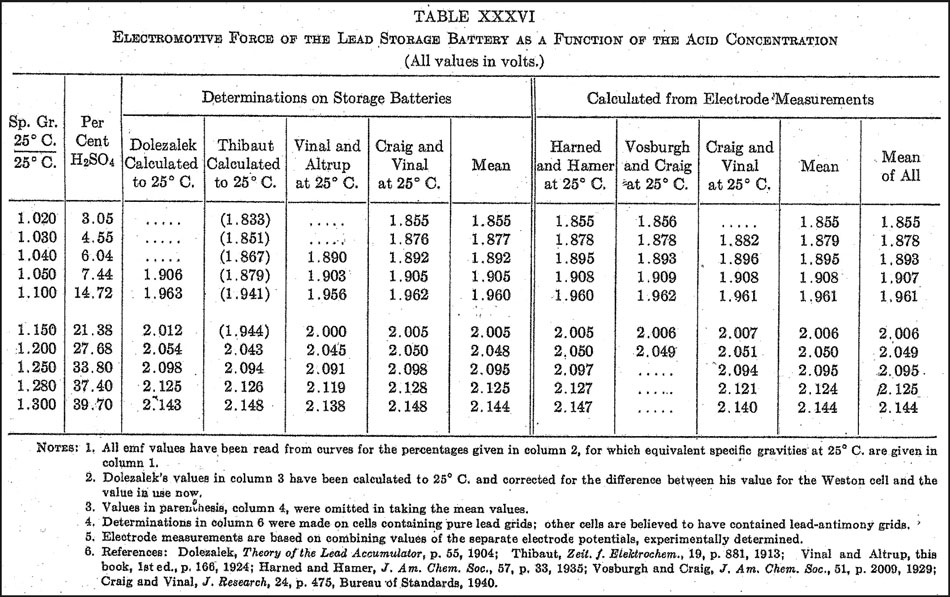
showing that internal resistance has not changed significantly over the years. The present model uses the value obtained in equation 1. Battery voltage gradient is the ratio of the voltage range to the battery capacity. Cell voltage varies directly with specific gravity SG15, reflecting the percentage of sulfuric acid in the electrolyte. At full charge, all the acid is in solution and SG is maximum. During discharge, acid reacts with the lead battery plates to form lead sulfate, decreasing SG. Vinal16 reported that the electrolyte SG of aircraft batteries was 1.300, to minimize the risk of electrolyte freezing at altitude. He also stated17 that acid concentrations less than 4.3% were below the operating range of storage batteries. Table 1 (Vinal’s table XXXVI), shows that a 4.3% concentration (column 2) is between the values corresponding to SG 1.020 and 1.030. Interpolating gives the corresponding SG value of 1.02833. The present model assumes an SG operating range of 1.030 to 1.300.
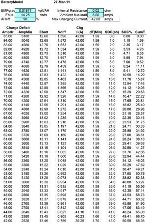
Vinal’s table also gives two sets of battery cell electromotive force (EMF) values versus specific gravity, obtained by researchers from 1904 to 1940. The values are for the open-circuit case, i.e. when the battery is at rest with neither a load nor a charging source connected. Vinal noted18 that the mean values of the determinations on batteries agreed reasonably well with the mean values calculated from electrode measurements. The values in the last column, the means of all the reported means – and thus the most probable values – are used in the present model. The overall mean open-circuit single-cell voltage range is 1.878 to 2.144 volts for an SG range of 1.030 to 1.300, hence the corresponding range for a 6-cell battery is 11.268 to 12.864 volts. Rounding to two decimal places gives the range as 11.27 to 12.86 volts, i.e. 1.59 volts, and the Exide 6-FHM-13 gradient is: (12.86 - 11.27)/85 = 1.59/85 = 0.01871 volt per AH. [Equation 3] Vinal notes that when a battery is placed on charge, the voltage jumps by about one volt19 due to displacement of acid from the pores of the battery plates. In the case of NR16020, when the on-bus battery received charge it was charging toward the bus voltage of 14.25 volts, but the voltage range would still be 1.59 volts, i.e. 12.66 to 14.25 volts, and the gradient would still be 0.01871 volt per AH. Model Implementation The model is implemented as an Excel 2007 spreadsheet, shown in Table 2.
The five blue cells in the top section allow variation of input parameters for excursion analysis. The values shown are those discussed above.
The model begins with the battery at zero charge and increments charge in one-AH steps. Since the battery will have 85 AH when fully charged, the initial charge deficit is 85 AH.
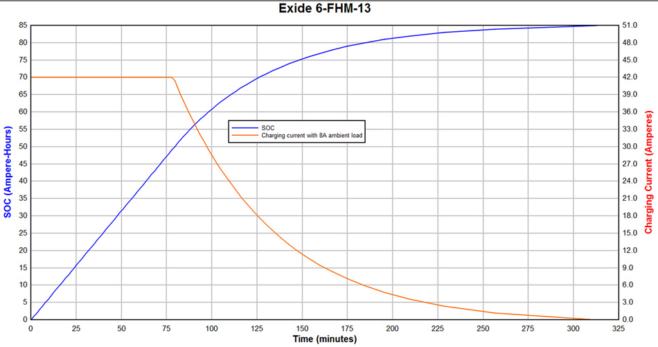
The curves in Figure 1 show state of charge (SOC) and charging current (Chg I) versus elapsed time (CumT). The total time to fully charge the battery, starting at zero charge, is 312.82 minutes.
Figure 1. Model Application At any given time, the battery SOC is at some point on the blue charge curve in Figure 1. When a transmission occurs, the charge taken from the battery moves the SOC to some lower point on the curve. If the generator is running after the transmission ends, the battery receives charge and the SOC increases, until the next transmission begins or until the engine is shut down. This process continues through the entire sequence of 57 signals, with the SOC moving up and down the charge curve. For example, if the battery SOC is 47 ampere-hours (74.60 minutes in the CumT column) and the battery is allowed to charge for 30 minutes without intervening loss of charge, the SOC will rise to the value corresponding to Cum T = 104.6 minutes, which is intermediate between the values corresponding to SOC 62.0 AH and 63.0 AH. Linear interpolation gives SOC = 62.82 AH at Cum T 104.6 minutes. Linear interpolation is appropriate because the charging curve can, for practical purposes, be considered piecewise linear within each one ampere-hour interval. Accounting for sequential charge gains and losses gives the SOC at every step along the signal transmission timeline. Conclusion The method used in developing the Exide 6-FHM-13 storage battery model is applicable to any storage battery for which the requisite operating parameter values are known.
|
||||||||||||||||||||||||||||||||||||||||||
|
||||||||||
|