Earhart Project Research Bulletin #72, cont.
October 25, 2014
The Window, the Patch, & the Artifact
Is TIGHAR Artifact 2-2-V-1 a piece of wreckage from Amelia Earhart’s aircraft?
Page 2
The Miami Patch
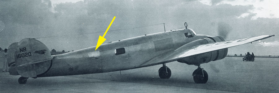
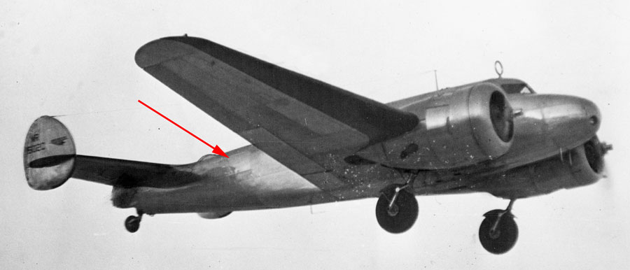
Earhart and Noonan departed Miami for San Juan, Puerto Rico early on the morning of Tuesday, June 1, 1937. A Miami Herald photo of the plane taxiing out for takeoff shows that some time between whenever the photo with Nilla Putnam was taken on Saturday and the departure for San Juan on Tuesday, the window had been replaced by a shiny aluminum patch. The patch is shiny because it is new aluminum and has not yet oxidized to gray like the rest of the airplane. No mention of this modification has been found in the various accounts of Earhart’s eight day stay in Miami, much less a justification for the change. What is certain is that the change was made.
As can be seen in this Miami Herald photo of the plane departing for San Juan, the patch was not flush with the surrounding skins but, like the window frame it replaced, was laid on top of the skins. This type of patch is known as a “scab patch.”
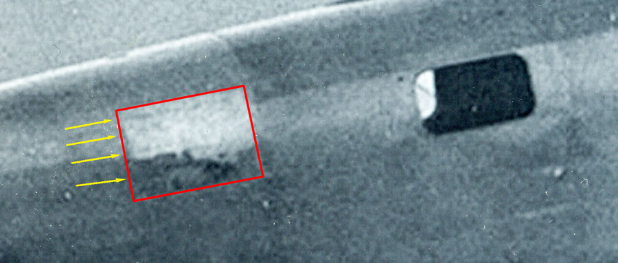
Forensic imaging of photos of the patch show that its borders were roughly the same as the window frame it replaced. Logically, they would be riveted to the same underlying structures that supported the window frame. Photo resolution is not sufficient to discern individual rivets on the scab patch but four longitudinal lines of rivets, spaced roughly four inches to add rigidity and prevent “oil-canning,” are visible. There are no vertical lines of rivets on the patch.
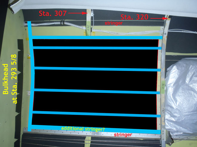
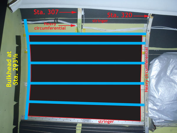
Given the spacing of rivet lines visible in historical photos of the patch, from the inside the structure had to look as shown above. This reconstruction of the patch is independent of Artifact 2-2-V-1 and is based entirely on analysis of historical photos of the patch, the known structures of the Lockheed Model 10, and standard aircraft repair practices.
The person who fabricated the patch — presumably Earhart’s own mechanic Ruckins D. “Bo” McKneely who was present in Miami — was faced with a challenge. As explained by another highly-experienced aircraft mechanic, TIGHAR researcher Jeffrey Neville:
The fuselage section in that area, Station 293 5/8 to Station 320, has a slight compound curvature in the skins. The original skins were formed to accommodate this graceful and strong shape, but making a flat piece of .032 sheet stock take on the curves where it fastened and behave well in service was likely a bit tough: the new sheet, being flat in natural form, wants to behave like a section in a cylinder, whereas it must attach at the edges where the more convex compound curvature in the original skin shape is realized (rather like the shape of an old-fashioned wooden barrel, not a cylinder section).
As the skin was fastened on with more fasteners as the work progressed, the installer likely had to deal with some deforming tendencies which impart both a slight “puckering” effect (think “fat wrinkles”) as more rivets were installed, and likely some “oil canning” tendencies. The expedient remedy for that can be the addition of light bracing, i.e. “stiffeners.” The pattern seen on photographs of the patch and on 2-2-V-1 reflect a logical approach to this solution given the window aperture size and the amount of compound curvature present — not so much curve that it couldn't have been overcome, but apparently enough to require some innovative bracing.
Gradualism is the key when working a fairly large flat sheet into conformance in such a situation, and more stiffeners can work better than one or two to help coax the metal into place as rivets are driven toward completion of attachment. Multiple stiffeners would also tend to help stabilize the sheet against a tympanic oil canning effect which is the natural outcome of applying a large flat panel over an aperture of this size. Oil canning (flexing in and out) is undesirable esthetically and functionally — Earhart likely did not want the window covering to be obvious, and oil canning can be noticeably loud in flight (popping sounds). It can also actually be fatiguing to the structure; stability is the key need.
Where the four stiffeners were placed was likely dictated by a hands-on evaluation as the work progressed, and obviously it was thoughtfully done as evidenced by the straight fastener lines and equal rivet spacing. The spacing between the four lines is slightly more erratic, as there is some noticeable odd convergence and divergence: they are not entirely parallel, and they do not all converge normal to the reduction in barrel section as one moves aft. This effect strongly suggests the nature of the task in the field of molding a flat sheet into submission in this area by able hands working with limited time, materials and tools: one braces where one gets the desired effect. What we see in 2-2-V-1’s puzzle of fastener lines where stiffeners once were appears to be the end result of just such an effort.
Note that none of the added longitudinal stiffeners ties into a cut stringer. That was not an option without removing the heavy lavatory bulkhead at Sta. 293 5/8. It is not possible from the photographs to tell the thickness of the aluminum sheet, but, according to FAA Flight Standards District Manager Aris Scarla*, standard practice is to make a scab patch the same, or preferably, one thickness greater than the surrounding skins. The surrounding skins on the Electra are .025″ so the scab patch should have been .032″. Artifact 2-2-V-1 is .032″ in thickness.
*Mr. Scarla participates in TIGHAR’s research as a private individual and not as a representative of the Federal Aviation Administration.
Testing the Hypothesis
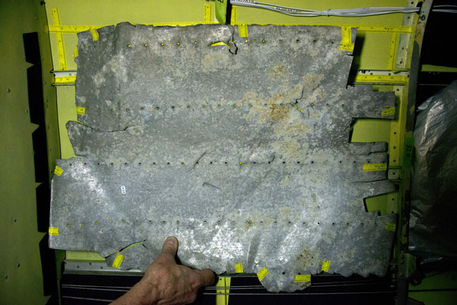
TIGHAR’s hypothesis is that Artifact 2-2-V-1 is the patch installed on NR16020 in Miami. In this photo, Artifact 2-2-V-1 is held against the interior wall of c/n 1091 in the space where the patch was on Earhart's aircraft. (The rectangular “coupons” cut from the artifact were removed by various laboratories for materials analysis.) Because the artifact is necessarily several inches closer to the camera than the skin of the aircraft, it appears to be a bit too big to fit. That’s an illusion. As forensic imaging specialist Jeff Glickman explains, “While not intuitive, this is a common optical illusion. It results from two radius curves that are intended to overlay upon each other, but instead have been separated. The origin of the illusion becomes apparent when the two radius curves are looked at in profile and their edges projected down to a 2 dimensional plane.”
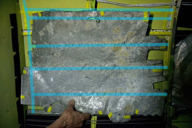
Overlaid against the structures added to Earhart’s aircraft to accommodate the window and later the patch, the rivet lines on the artifact match the rivet lines on the patch. The tear in the artifact at top center coincides with the heavy circumferential structure at Sta. 307.
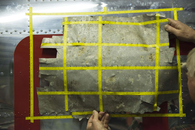
In this photograph, Artifact 2-2-V-1 is held against the exterior of c/n 1091 in the space (outlined with tape) where the patch was on Earhart’s aircraft. The distortion in this photo is less because the artifact is closer to the aircraft than was possible on the interior, but the artifact still appears a bit bigger than it would if it was in exactly the same plane (no pun intended) as the aircraft skin.
The artifact clearly fits within the boundaries of the patch with sufficient room to accommodate the various failures exhibited on its edges.
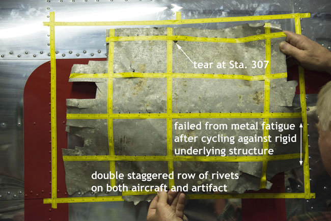
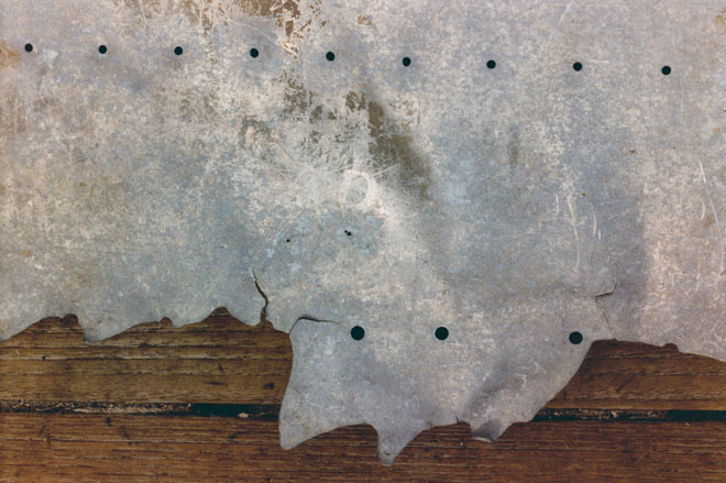
The bottom right edge of the artifact failed from metal fatigue after cycling back and forth against a straight rigid underlying structure. If the artifact is positioned longitudinally so that the bottom right edge abuts the underlying structure evidenced in photos of the patch, the tear in the metal on the top edge of the artifact aligns with where the patch was riveted to the stub of the heavy circumferential stiffener at Sta. 307. The bottom edge of the artifact tore along a double staggered row of rivets. The matching row of rivets on the Model 10 is a double staggered row.
However, the rivet holes on the artifact indicate the use of larger rivets (5/32″ rather than 3/32″) than were used on the window frame; and the space between the two lines of rivets in the staggered row implies the addition of another stiffener.
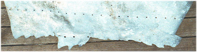
The pitch (distance between rivets) along the bottom edge of the artifact is irregular in stark contrast to the precise pitch of the parallel 3/32″ rivet lines. The metal sheet tore along the bottom line of rivet holes like a piece of paper tearing along a perforation. The rivets didn’t fail, the skin failed. At a point where there is a pronounced gap in the perforation, the tear jumped to the second line of rivets before jumping back to the first line, thus creating a “tab” of metal.
These are important clues to what happened, clues we don’t yet understand — but with the right expert help we’re confident that the picture will emerge.
Another puzzle is the etched remnant of what appears to be a portion of the original manufacturer’s labeling of the aluminum sheet. The letters AD, presumably part of the word ALCLAD, are visible on the exterior surface of the artifact. Some of our earlier interpretations of the labeling, based on opinions offered by ALCOA engineers have proved to be in error. Photos show that the ALCOA labeling on aluminum Lockheed used to build Earhart’s aircraft in 1936 abbreviated ALCLAD to ALC, but the patch dates from a year later and was not fabricated by Lockheed. More research is needed.
The Null Hypothesis
Although many questions remain to be answered about Artifact 2-2-V-1, it is instructive to consider the alternative explanation. If the artifact is not the scab patch from NR16020, then it is a random piece of aircraft wreckage from some unknown type involved in an unknown accident that just happens to match the dozens of material and dimensional requirements of the patch. This incredibly specific, but random, piece of debris just happened to end up on Nikumaroro, the atoll where so much other evidence points to Earhart.
Conclusion
TIGHAR finds the hypothesis that Artifact 2-2-V-1 is the patch installed on NR16020 in Miami to be strongly supported. Research will continue to seek answers to remaining questions about this wonderfully complex artifact, including defining and quantifying the type and magnitude of the forces necessary to cause the damage exhibited by the artifact. Those answers may strengthen or weaken the artifact-as-patch hypothesis but they will certainly inform our search for the rest of the aircraft.
Copyright 2021 by TIGHAR, a non-profit foundation.
No portion of the TIGHAR Website may be reproduced by xerographic,
photographic, digital or any other means for any purpose. No portion
of the TIGHAR Website may be stored in a retrieval system, copied,
transmitted or transferred in any form or by any means, whether electronic,
mechanical, digital, photographic, magnetic or otherwise, for any purpose
without the express, written permission of TIGHAR. All rights reserved.

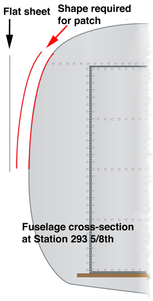 The fuselage section in that area, Station 293 5/8 to Station 320, has a slight compound curvature in the skins. The original skins were formed to accommodate this graceful and strong shape, but making a flat piece of .032 sheet stock take on the curves where it fastened and behave well in service was likely a bit tough: the new sheet, being flat in natural form, wants to behave like a section in a cylinder, whereas it must attach at the edges where the more convex compound curvature in the original skin shape is realized (rather like the shape of an old-fashioned wooden barrel, not a cylinder section).