 |
October 7, 2003
| Initial Report on the Dado |
This report was researched and written for TIGHAR by former TIGHAR member Frank C. Lombardo in 1994. While including some inaccuracies, it was a very important first step in understanding this artifact. Corrections have been made only to obvious typographical errors and to the artifact number itself.
NR16020
– An Analytical View
2-1-V-18 Dado
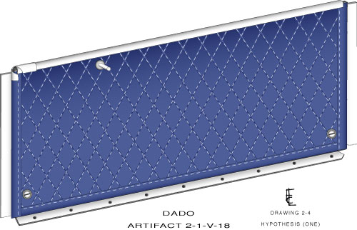
On October 4, 1989 the TIGHAR expedition to Nikumaroro in search for the wreckage of Lockheed NR16020, recovered a piece of aircraft structure, a piece of weathered aluminum material which they documented as artifact 2-1-V-18:
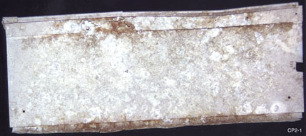 |
Dado 2-1-V-18, Front View, left.
|
The following paragraph was taken from report number 92-40, written by the NTSB laboratory after their examination of said artifact on March 5 1992.
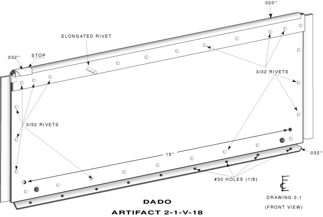
The riveted aluminum sheet metal assembly (dado) was made up of at least four separate components, a wide web (.032 inch thick) and a 90 degree flange (.022 inch thick). Overall, the assembly was 16 3/4 inch long by 6 1/2 inch wide. All four edges of the web appeared to be manufacturer's cuts with 3/32 inch diameter rivet holes and remnants of rivets nearby. The 90 degree flange was attached to one long edge of the web by rivets spaced 1 3/4 inch apart. The 180 degree flange and the flat strip were riveted to opposite sides of the other edge of the web.
Corrosion of the assembly components was heavy with the areas of the 180 degree flange and flat strip showing perforations. The space between the flange, web and strip was filled with corrosion products.
A long rivet tail, was located in the area of severe corrosion. During optical examination, small remnants of a bluish woven fabric were found around the rivet tail.
The following pages can be considered as a continuation of the report found on page 67 of TIGHAR’s “The Earhart Project: An Historical Investigation,” 7th edition, May 11 1993.
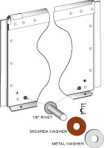
It was found that there were some minor discrepancies in the NTSB’s measurements of 2-18. The 90 degree bent material was not found to be of .022 inch but of .032 inch. The NTSB failed to mention that the “u” shaped strip of aluminum that traverses the width of the dado was constructed of .022.
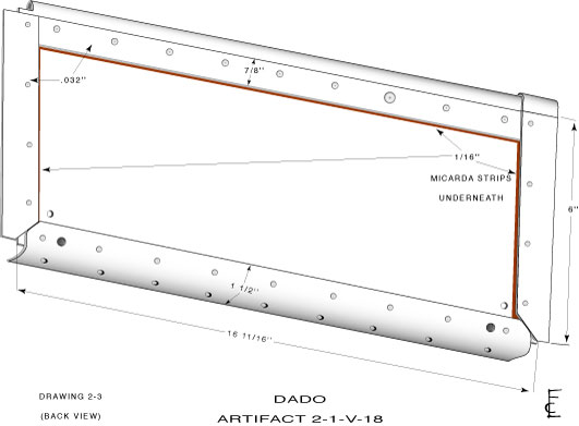 One
very important item that the NTSB had not mentioned was the 1/16 inch
thick micarda strips that were used in the construction of the web. On
the backside of the dado between the four strips of aluminum that border
the main body, each had a strip of micarda sandwiched between each support
strip and the main body. (Click on the small drawing at right to see a
larger version in a new window.) On the lower outboard portion of the
main body, two micarda washers were installed between a metal washer and
rivet; see drawing below.
One
very important item that the NTSB had not mentioned was the 1/16 inch
thick micarda strips that were used in the construction of the web. On
the backside of the dado between the four strips of aluminum that border
the main body, each had a strip of micarda sandwiched between each support
strip and the main body. (Click on the small drawing at right to see a
larger version in a new window.) On the lower outboard portion of the
main body, two micarda washers were installed between a metal washer and
rivet; see drawing below.
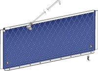
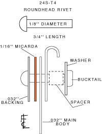 The
elongated fastener that appears on the left upper portion of the dado
is a 24S-T4 1/8 inch rivet. When new, was approximately 3/4 inch long.
The drawing at left illustrates how the rivet was installed.
The
elongated fastener that appears on the left upper portion of the dado
is a 24S-T4 1/8 inch rivet. When new, was approximately 3/4 inch long.
The drawing at left illustrates how the rivet was installed.
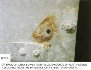
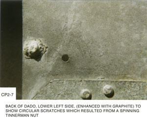
At each corner of the main body there are two 1/8 inch drilled holes, 15 inches apart, one on each side. Looking at the backside of the dado there is strong evidence of a rust residue at one hole, (photo CP2-6, below left) which would indicate presence of a steel fastener not unlike a tinnerman nut. At the opposite hole there are no rust stains, but evidence of circular scratches (photo CP2-7, below right) that could be caused by a spinning tinnerman nut. The spinning of the nut occurred with the mechanic’s effort to tighten the associated screw without the nut being secured down. It would be safe to say that tinnerman nuts and number 6 “pk” (parker-kalon) screws were used in securing the dado to the vertical supports of an aircraft that would have been spaced 15 inches apart center to center. Incidentally, 15 inches are the average distances between circumferentials and stiffeners of a Lockheed L-10.
 |
 |
The entire construction of this dado appears to be not of a production run type. Many cuts and bends are rough, showing signs of “hand made,” indicating that this could have been an afterthought. Something that was made in a hurry, for a custom fit.
Notice on the accompanying drawings, that many dimensions that were not mentioned by the NTSB are now known.
Elongated Fastener
The aluminum 1/8 inch, 24S-T4 roundhead rivet was ±1/4 inch long. Roundhead rivets had been discontinued for use on aircraft sometime in the 1940s.
Notice on the early photographs taken at about the time the NTSB laboratory was doing its test analysis on 2-1-V-18, that the area around the long rivet shows corrosion well far in advance. More so than on any other portion of the web. This acceleration was due to electrolysis between two dissimilar metals, or metals of the same properties but contaminated with moisture. This infection came from the rivet and a spacer that was inserted over the rivet shank to ensure bucking of the rivet to achieve a proper bucktail (see drawing detailing layers above). At this time, there are still remnants of the spacer on the rivet body itself and can be seen in recently taken photographs.
Bluish Woven Fabric
The small remnants of woven fabric found around the elongated rivet is believed to be small fibers from a larger piece of material of an insulation blanket that was used to cover the exposed side of the dado.
The 1/4 inch thick insulation blanket was made up of three separate layered pieces. The first layer, next to the body of the dado, was a thin sheet of translucent material (not identified at this writing) which was called a moisture barrier. This served for the purpose of keeping condensation from penetrating the insulation material.
The second layer was the insulation material called kapok, used liberally in aircraft in the thirties and in united states military aircraft during the second world war. The brand name of this material at that time was called Skyfelt or Seapak. It was used in Lockheed L-10 and L-12 interiors.
The third layer called felt was for cosmetic purposes and to hold the kapok in place. It came in a variety of colors, including the famous dark green that was seen in many military aircraft during world war two. The blanket came in three thicknesses, 3/4 inch, 1/2 inch and the most widely used 1/4 inch.
Where Did the Dado Come From?
As explained earlier, dados are generally found in the cabin area mounted from the floor up, as high as 3 to 10 inches, along the sides of the walls. They have more than one purpose. The most important of which is the protection of any control cables, hydraulic lines, electrical wiring or ducts that would run behind the interior fabric in the walls. This protection is needed here because of the passenger foot, baggage or cargo that accidentally strike the interior walls from time to time at floor level. One other use is to prevent dirt and other objects from falling around the edges of the floor boards and down into the bilges.
 Photographs of
the interior of NR16020 have shown that dados were not used on the left
or right sides or on any portion of the forward section of the cabin including
slanting bulkhead and main spar. We do know that there is photographic
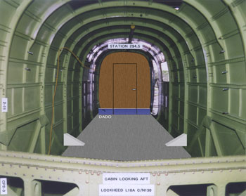
evidence of a rear bulkhead, located just inside the main cabin door.
Photographs of
the interior of NR16020 have shown that dados were not used on the left
or right sides or on any portion of the forward section of the cabin including
slanting bulkhead and main spar. We do know that there is photographic
evidence of a rear bulkhead, located just inside the main cabin door.
Lockheed aircraft had designed this optional bulkhead to be removable. With a door, a small closed in area had been created for the purposes of a baggage compartment or a toilet.
The dado (2-18) came from either the toilet or baggage area, or from the left or right of the bottom portion of the bulkhead (cabin side) or from the door itself (see photo left).
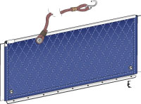
If the dado was positioned to the left of the door or on the door itself (looking aft) a hook or catch (see drawings below) could be attached to the fastener on the dado for the purpose of both holding the door open in flight or on the ground with the aircraft in a nose up configuration. The door most likely will not stay open without some type of restraint.
 |
 |
For What Purpose Was the Elongated Fastener Used?
The long rivet was placed in the dado for use as an attach point for some other function not related to the dado and was not used in any way to help support the dado to aircraft structure. It appears to be an afterthought, something that was not normally considered when the dado was designed and fabricated. The fastener was installed after the dado was fitted to the aircraft.
The simple fact that a extra long rivet (with spacer) was used, implies that whatever was to be attached, would have to use the shank body for a “wrap-around” configuration or some type of fixture with a hole in it to fit over the shank or a spacer on the rivet.
It should be pointed out that whatever the attachment here, this design could not withstand a great amount of stress or support such a heavy weight or pull forces.
Two Rivets Located at Bottom Outboard Corners
These
two 1/8 inch rivets had micarda washers installed between the main body
and a metal washer before they were set. They appear to be part of the
original design of the dado but were not utilized in the final configuration.
Their placement on the main body serve no function.
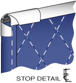 The
Stop
The
Stop
The insulation had a bead sewn around its border. The material was installed by inserting the top bead into the “u” shaped track and sliding it from right to left. The stop., installed on the upper left-hand corner of the dado prevented the material from moving any further than the left edge of the main body. However, the stop was not needed in the final configuration, because of the elongated rivet and the two, “pk” mounting screws with countersunk finishing washers, that would have held the insulation firmly in place. This meant that the insulation could not be removed or slid in any direction. This further proves that the dado’s final fabrication was quite different than its original intent.
![]() Photograph
CP2-4, right, shows remnants of the spacer surrounding the shank of the
elongated rivet on the dado.
Photograph
CP2-4, right, shows remnants of the spacer surrounding the shank of the
elongated rivet on the dado.
Photograph cp2-5, below, shows the scoring that appears at each of nine 1/8 inch holes on the under side of the 90 degree bend. This would be the portion of the dado that is secured to the floor with nails, “pk” screws, or wood screws. Each hole has the same three grooves that appear to be in the same direction and on the same side of all nine holes.
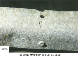
How the Grooves or “Scoring” Came About
#1. Before the angle was bent to 90 degrees, a rotex or greenleaf tool was used to fabricate the 9 holes. As each hole is “punched” the tool has a tendency to stick at each exercise and must be removed by an additional tool by forcing and prying the metal from the punch. Limited for space this “prying” tool can only be inserted into the punch in one direction … This is the pattern that is seen …
#2. Other than being exposed to the elements for over fifty years, there is no evidence of the dado being damaged by explosion, crash, or being hurriedly ripped out of the aircraft. It appears to be in remarkably good shape. The evidence is strong that the dado was installed, and at some later date removed by someone. By taking out the two mounting “pk” screws on the lower right and left sides, and if nails were used to hold the dado down, a tool was used to pry up the 90 degree angle aluminum from the floor … This is the pattern that is seen … If screws were used, and a screwdriver was not available, the same scenario would apply.
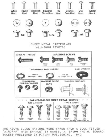
Screws and Fasteners