The eleven artifacts are displayed
in figures 1 through 11. Nine of the ten artifacts were either individual
pieces of aluminum sheet or assemblies of aluminum sheet pieces. The
other two artifacts were a "instrument panel" piece made from a phenolic
like material with an attached copper cylinder and the second, a strand
of solid wire. All the artifacts showed various levels of extensive corrosion,
erosion and other damage. The pieces are listed in Table A by the identification
number assigned by the investigator.
The artifacts were individually examined with a stereo
optical microscope with the observations noted below. In addition, small
specimens were removed from each of the aluminum sheet pieces and metallographic
cross sections were prepared then etched with Keller's Reagent to reveal
the microstructures. The majority of the pieces exhibited microstructures
consistent with a solution heat treated and aged core material sandwiched
between thin layers of relatively pure aluminum cladding generally referred
to as "Alclad". Photographs (50X) of representative microstructive areas
of some of the artifacts are shown in figures 1, 2B, 3 thru 6, 7B, 8
and lOB. Energy dispersive Report No. 92-40 X-ray analysis (EDXA) spectra
were acquired from the core region on each of the cross sections and
compared with the spectra from a 2024 aluminum alloy standard acquired
under the same electron beam conditions. Those specimens with spectra
consistent with 2024 are listed as "2024" in the "Alloy" column of Table
A, other spectra are listed as "not 2024". EDXA spectra from each sample
are attached to this report.
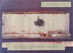
2-2-V-1 Sheet
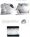 The
sheet was a comparatively large piece (23 inch x 19 inch) of 0.032 inch
thick aluminum alloy, shown in
figure 1, with a pronounced curvature across the short dimension.
The sheet had four rows of evenly spaced 3/16 inch diameter rivet holes
and one row of 5/32" holes along its long dimension. Measurements determined
that the rivet rows were not parallel but rather showed a slight convergence.
Nominal spacing between rows was about 4-1/4 inches at one end of the
sheet and 1/8 to 1/4 inch closer at the other end. The skin around these
holes was, in general, dimpled inward toward the concave side of the
sheet suggesting that the sheet had been area loaded from the concave
side while the rivets and underlying structure were intact. The remains
of a solid brazier-head rivet were found in the hole denoted by arrow "R" in
figure 1. The manufactured head of the rivet was on the convex side of
the sheet and was marked with a single round dimple in the center of
the head, as shown in the right center photograph of figure 1. The dimple
usually signifies a 2117 aluminum alloy rivet. The length of the undeformed
rivet shank (distance between the manufactured head and the formed head)
indicated that the skin had previously been attached to an approximately
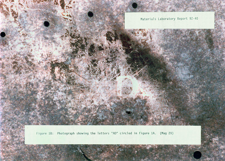
0.06 inch thick underlying member. The faint outline of 1/2" tall letters "AD" were
noted on the convex side of the sheet in the circled area in figure 1A
and are shown at 2X in figure
lB. The
sheet was a comparatively large piece (23 inch x 19 inch) of 0.032 inch
thick aluminum alloy, shown in
figure 1, with a pronounced curvature across the short dimension.
The sheet had four rows of evenly spaced 3/16 inch diameter rivet holes
and one row of 5/32" holes along its long dimension. Measurements determined
that the rivet rows were not parallel but rather showed a slight convergence.
Nominal spacing between rows was about 4-1/4 inches at one end of the
sheet and 1/8 to 1/4 inch closer at the other end. The skin around these
holes was, in general, dimpled inward toward the concave side of the
sheet suggesting that the sheet had been area loaded from the concave
side while the rivets and underlying structure were intact. The remains
of a solid brazier-head rivet were found in the hole denoted by arrow "R" in
figure 1. The manufactured head of the rivet was on the convex side of
the sheet and was marked with a single round dimple in the center of
the head, as shown in the right center photograph of figure 1. The dimple
usually signifies a 2117 aluminum alloy rivet. The length of the undeformed
rivet shank (distance between the manufactured head and the formed head)
indicated that the skin had previously been attached to an approximately
0.06 inch thick underlying member. The faint outline of 1/2" tall letters "AD" were
noted on the convex side of the sheet in the circled area in figure 1A
and are shown at 2X in figure
lB.
 The
sheet was bounded by fractures on all four sides. On one side the fracture
ran generally along the line of larger 5/32 inch diameter rivet holes.
The fracture intersected all of the 5/32 inch diameter holes except for
the three denoted by arrows "H" figure 1. The rivet holes in this row
were nominally spaced at 1-1/4 inch intervals except for the three unfractured
holes which were not evenly spaced. Post separation abrasion and erosion
damage had obliterated the fracture faces and positive determination
of the modes of fractures could not be established. However, the fracture
geometry along the line of rivet holes (upper edge of sheet in figure
1) was consistent with tearing separations in both directions away from
the area of the intact holes, as indicated by the unlabelled arrows in
the upper photos of figure 1. Also, deformation adjacent to the fracture
line located by brackets in figure 1 indicated that the sheet had been
folded 90 degrees toward the convex side prior to separation. The
sheet was bounded by fractures on all four sides. On one side the fracture
ran generally along the line of larger 5/32 inch diameter rivet holes.
The fracture intersected all of the 5/32 inch diameter holes except for
the three denoted by arrows "H" figure 1. The rivet holes in this row
were nominally spaced at 1-1/4 inch intervals except for the three unfractured
holes which were not evenly spaced. Post separation abrasion and erosion
damage had obliterated the fracture faces and positive determination
of the modes of fractures could not be established. However, the fracture
geometry along the line of rivet holes (upper edge of sheet in figure
1) was consistent with tearing separations in both directions away from
the area of the intact holes, as indicated by the unlabelled arrows in
the upper photos of figure 1. Also, deformation adjacent to the fracture
line located by brackets in figure 1 indicated that the sheet had been
folded 90 degrees toward the convex side prior to separation.
2-2-V-9 Channel Section
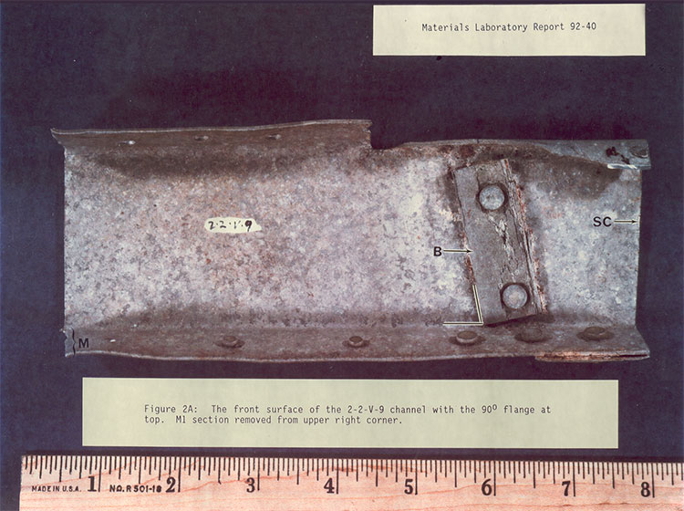
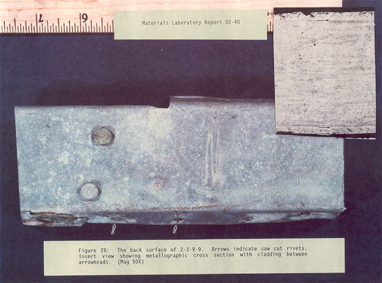
The 2-2-V-9 artifact was a "C" shaped formed aluminum sheet channel approximately
7.25 inch long by 3 inch wide with a nominal material thickness of 0.062
inch and is shown from both sides in figures 2A and 2B.
Visual examination indicated that one end of the channel had been transversely
saw cut through the entire cross section arrowed "SC" in figure 2A. The
other end also exhibited saw cut marks but only partially through the section
thickness. The remaining section thickness was bent and broken at the cut.
The channel had a 2-3/8 inch wide web and two 3/4 inch wide riveting flanges,
one at 90 degrees to the web and the other at about 110 degrees. The 90
degree flange had several 3/8 inch rivet holes set at 7/8 inch spacing,
with a formed solid rivet remaining in one hole. The 110 degree flange
had three 5/32 inch diameter holes containing rivet pieces and also had
three complete 3/16 inch rivets. The shanks of two of the rivets (one 5/32
and one 3/16) had been partially saw cut from the outside of the channel.
A portion of a flange or bracket (arrow "B" in figure 2A) was riveted to
the inside surface of the web. The bracket piece was severely damaged by
exfoliation corrosion but remained firmly attached to the channel by two
3/16 inch diameter rivets. The long axis of the bracket piece was set at
an approximate 80 degree angle to the longitudinal direction of the channel.
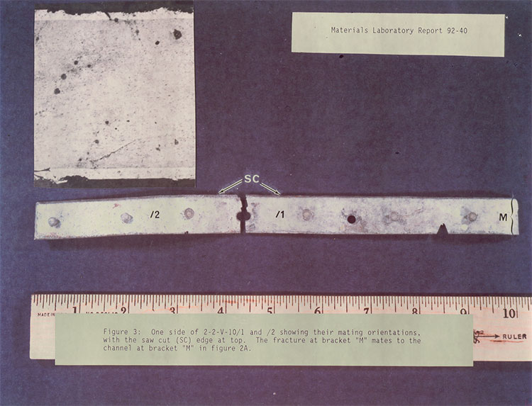
2-2-V-10 Two Strips
 The
two strips were 0.063 inch thick aluminum alloy which fracture matched
along a transverse bending overstress fracture, as shown in figure
3. Each strip was about 3/4 inch wide, with one about 5-5/8 inch
long and the other 4-1/4 inch long. The two strips were labeled "/1" and "/2",
respectively. The end of "/1" located by bracket "M" in
figure 3, was also a bending overstress fracture, which upon close inspection
mated to the fractured end of the 110 degree flange on the channel piece,
2-2-V-9, in the area of bracket "M" in figure
2A. The non-mating end of the "/2" strip was saw cut half
way through and then overstress broken. The two strips had a single line
of 5/32 inch rivets with irregular spacing. One long edge of both strips
appeared to have a manufactured edge while the other edge appeared to
have been saw cut along the bend radius between the flange and the web
of the channel. The
two strips were 0.063 inch thick aluminum alloy which fracture matched
along a transverse bending overstress fracture, as shown in figure
3. Each strip was about 3/4 inch wide, with one about 5-5/8 inch
long and the other 4-1/4 inch long. The two strips were labeled "/1" and "/2",
respectively. The end of "/1" located by bracket "M" in
figure 3, was also a bending overstress fracture, which upon close inspection
mated to the fractured end of the 110 degree flange on the channel piece,
2-2-V-9, in the area of bracket "M" in figure
2A. The non-mating end of the "/2" strip was saw cut half
way through and then overstress broken. The two strips had a single line
of 5/32 inch rivets with irregular spacing. One long edge of both strips
appeared to have a manufactured edge while the other edge appeared to
have been saw cut along the bend radius between the flange and the web
of the channel.
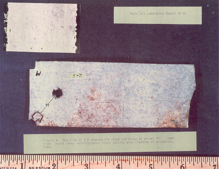
2-5 Plate
 The
2-5 plate was a small roughly rectangular piece, about 2 inch by 5 inch
by 0.062 inch thick, displayed in figure
4. The plate had a straight sheared edge (manufacturer's cut) along
one long side, a bending overstress fracture along one short edge and
the other two edges exhibited typical saw cut markings. A ragged hole
went through one end of the plate as if cut by multiple strikes with
a thin narrow instrument such as a small chisel or screwdriver. A second
similar hole was cut partially through the plate, see arrows "H". The
2-5 plate was a small roughly rectangular piece, about 2 inch by 5 inch
by 0.062 inch thick, displayed in figure
4. The plate had a straight sheared edge (manufacturer's cut) along
one long side, a bending overstress fracture along one short edge and
the other two edges exhibited typical saw cut markings. A ragged hole
went through one end of the plate as if cut by multiple strikes with
a thin narrow instrument such as a small chisel or screwdriver. A second
similar hole was cut partially through the plate, see arrows "H".
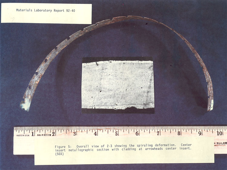
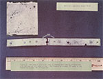
2-3 Strip
 Figure
5 shows a 14 inch long by 1/2 inch wide strip of 0.040 inch nominal
thickness aluminum alloy that was labeled as artifact "2-3".
The strip had a manufactured edge along one side and an unidentified
edge separation along the other side that intersected a line of 5/32
inch diameter holes. The holes were nominally spaced 3/4 inch on center.
The strip was deformed in a spiraling curl suggestive of the waste
side strip produced from cutting with a pair of tin snips. Figure
5 shows a 14 inch long by 1/2 inch wide strip of 0.040 inch nominal
thickness aluminum alloy that was labeled as artifact "2-3".
The strip had a manufactured edge along one side and an unidentified
edge separation along the other side that intersected a line of 5/32
inch diameter holes. The holes were nominally spaced 3/4 inch on center.
The strip was deformed in a spiraling curl suggestive of the waste
side strip produced from cutting with a pair of tin snips.
2-2-V-8 Riveted Assembly
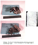 The
riveted assembly, shown as figure
6, was made up of two aluminum alloy members. One member was roughly
triangular in overall shape and appeared to be complete and relatively
undamaged. A small piece was removed for metallographic examination and
identified as section "M2", see Table A.
The other member was severely damaged by exfoliation corrosion making
it difficult to determine its original shape or configuration and no
metallurgical samples were removed. However, there were four identifiable
5/32 inch diameter rivet holes along one edge with the formed tail portion
of one rivet remaining. The two pieces of the assembly were connected
by three large 3/16 inch diameter intact rivets that were each marked
with a single dimple in their manufactured heads. The
riveted assembly, shown as figure
6, was made up of two aluminum alloy members. One member was roughly
triangular in overall shape and appeared to be complete and relatively
undamaged. A small piece was removed for metallographic examination and
identified as section "M2", see Table A.
The other member was severely damaged by exfoliation corrosion making
it difficult to determine its original shape or configuration and no
metallurgical samples were removed. However, there were four identifiable
5/32 inch diameter rivet holes along one edge with the formed tail portion
of one rivet remaining. The two pieces of the assembly were connected
by three large 3/16 inch diameter intact rivets that were each marked
with a single dimple in their manufactured heads.
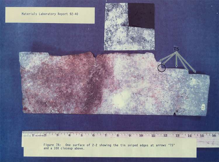
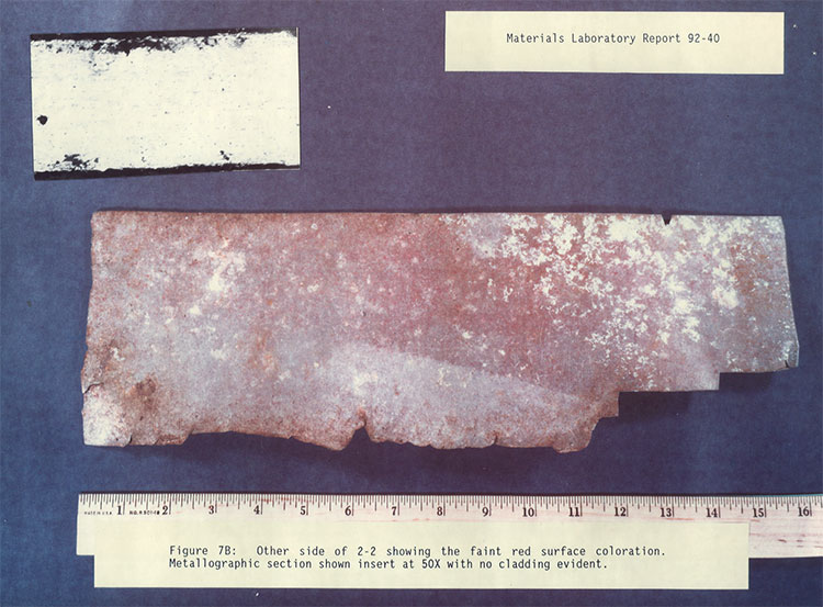
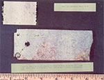
2-2 Sheet
The sheet was about 5-1/4 inch wide by 15-1/2 inch long and 0.032 inch
thick, as shown in figures 7A and 7B.
The long straight edge of the piece appeared to have been an original manufacturer's
cut. The piece appears to have been further mechanically cut along the
lines denoted by arrows "TS" in figure 7A. Magnified examination
of the inside corner intersections of these cuts revealed deformation patterns
typical of cuts made with a pair of tin snips, see insert photograph in
7A. The remaining edges of the sheet appeared to be typical tearing fractures.
One surface of the sheet had a rusty brown stain on about half of its area
(see figure 7A). The opposite surface had a faint red coloration over a
portion of its surface, as shown in figure 7B.
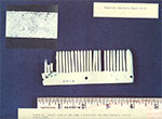 2-2-V-5
Comb 2-2-V-5
Comb
The comb was crudely formed as shown in figure
8, with parallel saw cuts separating the teeth. The comb was 3-7/8
inch long by 1-3/8 inch wide, made from 0.032 inch thick aluminum alloy
sheet. The comb had three 1/8 inch diameter holes nominally spaced
1-7/8 inch apart.
2-2-V-2 Panel
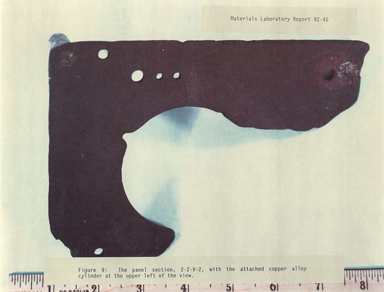
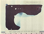 The
artifact shown in figure 9 appeared
to be a portion of an instrument mounting panel made from a flat piece
of Bakelite-like material. The panel section had a solid metallic cylinder
screw attached to one of the corners. The flat portion had several small
holes and a portion of a much larger hole. No metallurgical sections
were removed from this artifact. The
artifact shown in figure 9 appeared
to be a portion of an instrument mounting panel made from a flat piece
of Bakelite-like material. The panel section had a solid metallic cylinder
screw attached to one of the corners. The flat portion had several small
holes and a portion of a much larger hole. No metallurgical sections
were removed from this artifact.
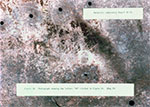
2-18 Dado
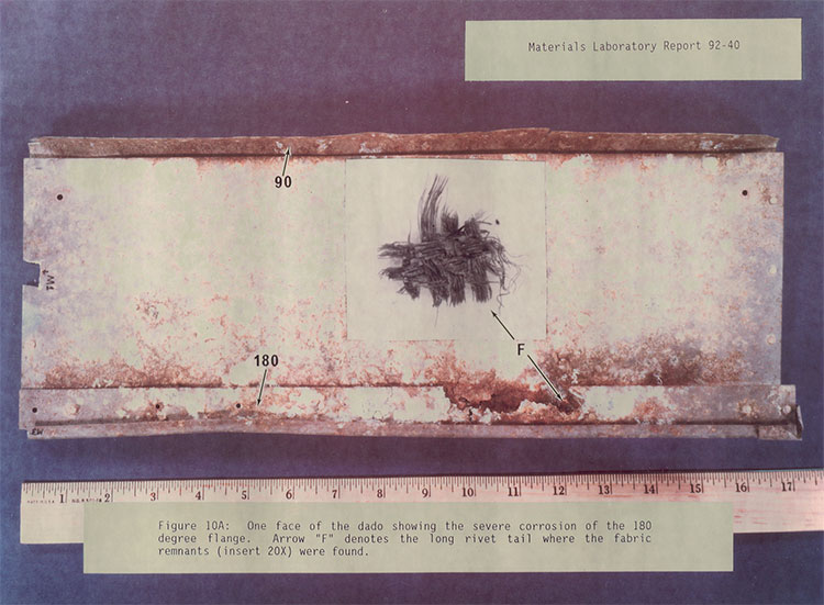
 The
riveted aluminum sheet metal assembly (Dado) in figure
10 was made up of at least four separate components, a wide web (0.032
inch thick), a narrow flat strip (0.022 inch thick), a 180 degree flange
(0.028 inch thick) and a 90 degree flange (0.022 inch thick). Overall,
the assembly was 16-3/4 inch long by 6-1/2 inch wide. All four edges
of the web appeared to be manufacturer's cuts with 3/32 inch diameter
rivet holes and remnants of rivets nearby. The 90 degree flange, arrowed "90" in
figure 10A, was attached to one long edge of the web by rivets spaced
1-3/4 inch apart. The 180 degree flange and the flat strip were riveted
to opposite sides of the other long edge of the web. The
riveted aluminum sheet metal assembly (Dado) in figure
10 was made up of at least four separate components, a wide web (0.032
inch thick), a narrow flat strip (0.022 inch thick), a 180 degree flange
(0.028 inch thick) and a 90 degree flange (0.022 inch thick). Overall,
the assembly was 16-3/4 inch long by 6-1/2 inch wide. All four edges
of the web appeared to be manufacturer's cuts with 3/32 inch diameter
rivet holes and remnants of rivets nearby. The 90 degree flange, arrowed "90" in
figure 10A, was attached to one long edge of the web by rivets spaced
1-3/4 inch apart. The 180 degree flange and the flat strip were riveted
to opposite sides of the other long edge of the web.
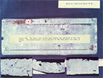 Corrosion
of the assembly components was heavy with the areas of the 180 degree
flange and flat strip showing perforations. The space between the flange,
web and strip was filled with corrosion products. Corrosion
of the assembly components was heavy with the areas of the 180 degree
flange and flat strip showing perforations. The space between the flange,
web and strip was filled with corrosion products.
A long rivet tail, arrow "F" in figure 10A, was located in
the area of severe corrosion. During optical examination, small remnants
of a bluish woven fabric were found around the rivet tail as shown in
the figure 1OA insert.
Metallurgical sections were removed from the web, (section Ml, with
a rivet piece), the 90 degree flange (section M2), the 180 degree flange
(section M3), and the flat strip flange (section M4).
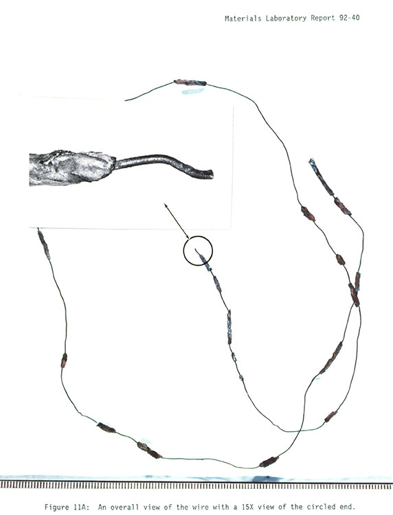
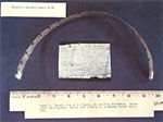
2-2-V-1 Wire
 The
wire (shown in figure 11A)
was reportedly found entangled in one of the tears of artifact 2-2-V-1.
The wire was a single strand of 0.024 inch diameter copper wire that
was 34 inches long. Remnants of what appeared to be degraded and hardened
insulation were found randomly along the length of the wire. Examination
of a portion of the insulation with the aid of a scanning electron microscope
(SEM) revealed fibrous strands, encased in the insulation jacket as denoted
by arrows "T" in figure 11B. The
wire (shown in figure 11A)
was reportedly found entangled in one of the tears of artifact 2-2-V-1.
The wire was a single strand of 0.024 inch diameter copper wire that
was 34 inches long. Remnants of what appeared to be degraded and hardened
insulation were found randomly along the length of the wire. Examination
of a portion of the insulation with the aid of a scanning electron microscope
(SEM) revealed fibrous strands, encased in the insulation jacket as denoted
by arrows "T" in figure 11B.
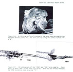 Samples
of reportedly common aircraft antenna wire labeled "1938" and "1941" were
also supplied by the investigator for comparison purposes and are displayed
in figure 11C. The "1938" wire sample had a single strand,
solid wire core with a easily fragmented inner insulation and a woven
fabric outer covering. EDXA analysis determined that the copper wire
core had been tinned prior to being insulated. The inner insulation had
two longitudinal fibrous threads, arrowed "T1" in figure 11C,
embedded within the insulation material. The wire sample labeled "1941" had
a similar outer covering but in contrast had a multiple strand twisted
wire core and a rubbery inner insulation with no indications of embedded
threads. Samples
of reportedly common aircraft antenna wire labeled "1938" and "1941" were
also supplied by the investigator for comparison purposes and are displayed
in figure 11C. The "1938" wire sample had a single strand,
solid wire core with a easily fragmented inner insulation and a woven
fabric outer covering. EDXA analysis determined that the copper wire
core had been tinned prior to being insulated. The inner insulation had
two longitudinal fibrous threads, arrowed "T1" in figure 11C,
embedded within the insulation material. The wire sample labeled "1941" had
a similar outer covering but in contrast had a multiple strand twisted
wire core and a rubbery inner insulation with no indications of embedded
threads.
|