

The International Group for Historic Aircraft Recovery
2812 Fawkes Drive
Wilmington, Delaware 19808
VIA: US MAIL FIRST CLASS AND FACSIMILE 302-944-7945
PRELIMINARY LETTER OF OPINION
Dear Mr. Gillespie,
I am in receipt of two photographs from TIGHAR of Ms. Amelia Earhart standing on the left wing of her Lockheed Electra 10E. I understand that both photographs are copies of the same photograph shot at different scales. I understand you need to know the size of the heel of Ms. Earhart’s right shoe seen in the photograph. I can measure the length of the heel, however, due to the orientation of the shoe with respect to the camera, and the availability of scale data, I cannot measure the width of the heel.
It is my understanding that TIGHAR has in its possession a recovered rubber heel from one of its expeditions, and that TIGHAR’s objective is to compare the length of the recovered rubber heel to the length of the rubber heel seen in the supplied photographs. To make a proper comparison, the recovered heel must cover the full length of a shoe heel. I have no prior knowledge of the recovered heel, and therefore I hereby certify and affirm that I do not currently know, nor have I ever known, any measurement information with respect to this recovered artifact.
The orientation of the heel (‘object’) seen in the photographs with respect to the camera is complex: there is minimal displacement of the object from the image y-axis, near maximum displacement from the image x-axis, and the object is rotated in all three dimensions. This complicates accurate analysis.
Analysis begins by establishing scale in the photograph. TIGHAR initially reported that the mean center-to-center distance between the rivet rows on the wing in the supplied photographs was 3.5 inches, and that this data was obtained by measuring the mean distance between wing rivet rows on a Lockheed 10. Subsequent retrieval of data from TIGHAR archives shows this distance to be 2.5 inches. The assumption is that all Lockheed 10s were constructed using common engineering drawings and that therefore all Lockheed 10s have a mean wing rivet row spacing of 2.5 inches, including Ms. Earhart’s. I have not independently confirmed TIGHAR’s measurement, however I shall use this datum in subsequent calculations.
The rivet rows are rotated with respect to the camera which restricts the way the above scale data can be used. The rotation means that separate anamorphic compression coefficients must be used, one each for the three orthogonal axes. Without knowing these coefficients, the scale data can be applied in the following restricted manner: The scale data is valid only in the family of parallel lines of corresponding rivets between two or more rivet rows, and further scaled by the vanishing perspective. There is no other valid orientation for use of the scale data.
Normally, repeated measurements along the above family of parallel lines would be used to establish the vanishing scale coefficient and measurement error bounds. There are however unique circumstances in this photograph which make this unnecessary. The first is a ridged surface which Ms. Earhart is standing on which is most easily seen in the close-up photograph. The second is that the ridges are in the same family of parallel lines as the rivet rows. The third is that the boundary separating the ridged surface from the rest of the wing is in the same family of parallel lines as the scale. Therefore, the ridges can be used to project the scale onto the side of the object.
At the interface of the wing surface and the ridged surface are 3 rivets belonging to the scale family of parallel lines. The first rivet (rivet 1) is near the ball of the foot, the second rivet (rivet 2) is near the arch of the foot, and the third rivet (rivet 3) is near the heel of the foot.
Sobel kernels were used to enhance the ridges. Vertical Sobel and horizontal Sobel kernels were applied to the close-up image and added together (Sobel Magnitude image). This image was inverted, and then its levels adjusted to visualize the ridges. This was then added to the original close-up image to enhance the ridges. This image was analyzed to count the number of ridges between rivet 1 and rivet 2, and the number of ridges between rivet 2 and rivet 3. In both cases, there are 20 ridges. As the mean distance is 2.5 inches between each row of rivets, and there are 20 ridges between each row of rivets, the center-to-center ridge spacing is therefore 0.125 inches, or 3.175 millimeters.
The ridges extend from the interface of the wing surface and the ridged surface, to the side of the object. This does not however provide sufficient information to measure the heel because of the oblique angle of the shoe with respect to the camera in the plane of the wing surface. The apparent length of the object is different than the actual length due to this oblique angle. It is therefore essential to determine this oblique angle to correct the object’s apparent length.
The top projection of the object is modeled as a rectangle and a half-circle which share one edge. The shared edge is the longer edge of the rectangle, and the linear edge of the half circle. The rectangle has dimensions l x w, where l in the length in the x-axis, and w is the length in the y-axis. The half-circle has constant radius r, such that the diameter d (d = 2r) is the same as w, therefore 2r = d = w. The length l of the rectangle is set to r, the same as the radius of the half-circle. The inside bottom edge of the heel may have curvature, however, the extreme points of such a symmetric arc form the corners of the model’s rectangle. The error introduced from divergence of the heel model from an actual heel is negligible and can be ignored.
The projection of the inside edge of the heel comprise 4 ridges. This measurement was made by following the vertical edges of the inside edge of the heel down to the point of contact with a ridge, and then counting the number of ridges between these two points of contact. To minimize error, the counting was made in the same family of parallel lines as the scale. Therefore, the projection of the inside edge of the heel is 0.5 inches or 12.7 millimeters.
The projection of the side of the heel comprise 16.5 ridges. This measurement was made by following the right-hand vertical edge of the inside edge of the heel, and the rear of the heal down to the point of contact with a ridge, and then counting the number of ridges between these two points of contact. To minimize error, the counting was made in the same family of parallel lines as the scale. Therefore, the projection of the side of the heel is 2.0625 inches, or 52.3875 millimeters.
These two projection measurements from the heel, when combined with the heel model, are sufficient information to calculate the angle of rotation of the heel away from the camera in the plane of the wing. The height of the camera relative to the plane of the wing is low, and the error introduced by this height is negligible and can be ignored.
The total projected length of the inside edge of the heel is (Equation 1):
![]()
where 2r is the approximate and unknown width of the heel, q is angle of rotation of the heel away from the camera, and 4 is the length (in ridges) of the measured projection.
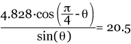
The total projected length of the side edge of the heel is (Equation 2):
![]()
where the first factor is the projected length of the half-circle plus the projected length of adjoining rectangle, the second factor accommodates the projection, q is angle of rotation of the heel away from the camera in the plane of the wing, and 20.5 is the length (in ridges) of the measured projection (the sum of 4 + 16.5, the two projections measured above).
These two equations constitute two equations in two unknowns which can be solved to determine q, the angle of rotation of the heel away from the camera.
Equation 1 can be rewritten as:
![]()
![]()
This equation was solved for q using Mathcad Professional 2000, resulting in q = 11.3°, the rotation of the heel away from the camera in the plane of the wing.
The measured value of 20.5 ridges is the projection of a diagonal measurement taken across the heel. This measurement must be corrected for both the heel rotation and the diagonality. Because the measurement is a diagonal measurement, it must be shortened to correct for the heel rotation. The diagonal measurement corrected for the heel rotation of 11.3°is 20.1 ridges.
The geometry of the diagonal measurement is used to determine the length of the heel. In the model, assuming no heel rotation, the diagonal measurement is at 63.43° relative to the inside heel edge. When the heel is rotated 11.3°, the right end point of the visible diagonal moves along the perimeter of the half-circle, obscuring the end of the heel. In the model, the diagonal at 11.3° is 3.5% longer than the diagonal to the rear of the heel. Therefore, the diagonal measurement corrected to the rear of the heel is 19.4 ridges. Now the diagonal at 63.43°is corrected into the family of lines parallel to the heel: 19.4 sin(63.43) = 17.35 ridges. Having previously calculated the center-to-center ridge width as 3.175 millimeters, the length of the heel is 17.35 (3.175) = 55.1 millimeters. I have not yet performed an error analysis to establish a confidence interval.
It may be possible to perform a similar computation to determine the length of the shoe. Also, to properly apply the above result, it is important to know if heel length is constant or varying with respect to shoe length.
Thank you for your continued interest in, and support, of PHOTEK.
Sincerely,
Board Certified Forensic Examiner
Fellow, American College of Forensic Examiners
www.PhotekImaging.com