 |
Due to the relatively good condition of the engine, the internal components and engine block were almost entirely intact. For this reason, much river debris and loose corrosion products still remained contained within. Although physical access to this was extremely limited, as much as possible was removed using vacuum extraction.
The externals of the object were mechanically cleaned of loose debris and concretions using brushes, probes and scalpels to a point where physical damage to metal surfaces would not occur.
A high pressure water spray was used for a final wash prior to immersion in the pre-treatment bath.
a. Preparation of Solution.
The nominal internal dimensions of the treatment tank were 2.05 metres by 1.8 metres and the required height of the solution required to cover the engine on its treatment stand was 1.2 metres. This corresponded to a liquid volume of 4,428 litres.
The buffered citrate solution was prepared in the ratio of 9.6g/1 anhydrous citric acid and 4.8 g/1 sodium hydroxide. Thus the total weight of chemicals required for the first pretreatment was 42.5 kg of anhydrous citric acid and 21.25 kg of sodium hydroxide.
b. Polarization of the Tank.
As mentioned earlier, the uncoated inside surface of the treatment tank was cathodically protected during the entire treatment process. An initial trial of the technique was first conducted.
The tank was polarized for three days before engine immersion and the pH was monitored, as was a visual observation of the colour of the solution. Although a slightly green colouration was imparted to the solution, the pH remained stable at approximately 5.2. This indicated that little dissolution of ferrous ions had occurred, demonstrating the effectiveness of the technique.
The power supply used was an ACORE type RGT444 with an output rating of 25V and 100A (this power supply was used throughout the treatment). Large, 2 cm diameter power leads were used to connect both anode and tank (cathode) to minimise voltage.
The tank was polarized to a value of -1. 2V/ SSE after an initial period of stabilization. The power requirement was very low, being approximately 2V and 5A.
c. Engine immersion.
The pH of the solution was closely monitored:
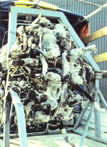
Prior to immersion
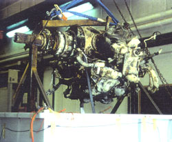
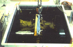
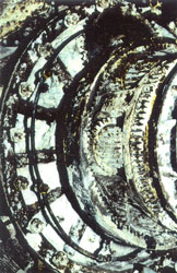
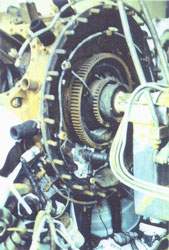
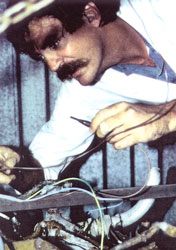
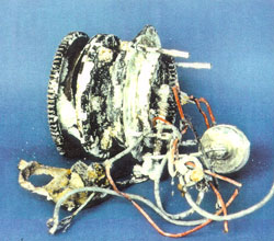
Figure 17 a and b, left and right. Immersion of engine for pretreatment. Although buffered, the pH rises slowly. This may be attributed to the dissolution of iron corrosion products. The consumption of the complexing ions by ferrous species leads to a decrease in buffer capacity. As the iron concentration levels out, so does the pH stabilize.
d. End of the Pretreatment.
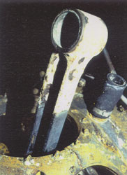
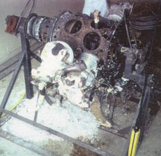
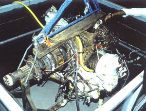
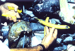
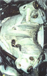
After 7 days of immersion the engine was removed from solution and washed down with high pressure water. It was noted that most of the superficial corrosion products and concretions had been removed from the ferrous alloys, which now had the typical black appearance of magnetite (fig. 18.). Riverbed debris, such as sand and small stones were still wedged within the fins of the cylinder heads and in other areas (fig. 19.). Magnesium alloy corrosion products were now quite soft, and were easily removed by mechanical methods. This process was conducted for approximately 1 week. As the front section of the engine was cleaned, the ferrous alloy “cam followers” were revealed. These were found to be unattached and were thus removed and treated separately.
Figure 18. After pretreatment. The iron components of the engine have the typical black appearance of magnetite. Note the presence of concretions on the upper portion of the piston rod which partially protruded from the solution during treatment. Left, after pretreatment. Right, after removal. Note the removal of the cam followers. Figure 19. Magnesium corrosion products found at the front of the engine could be easily removed by mechanical methods after the pretreatment.
The tank was filled with a total of 4,428 litres of 0.04M sodium metasilicate pentahydrate solution (MW 122.06). A total weight of 21.62kg was first made up as a concentrated solution in small tanks and diluted to the correct concentration in the larger treatment tank prior to the commencement of the treatment. During the process, a fine white precipitate formed in the tanks. It was speculated that this was due to the high carbonate content of the available tap water forming a precipitate with the high initial concentration of metasilicate, although this theory was never tested.
After the extensive mechanical cleaning described above, the iron components of the engine were prepared for polarization by connecting all major iron components using electrical wires and clamps. It must be remembered that this treatment stage is designed to treat the iron components only while inhibiting corrosion of the aluminium alloys (fig. 20).
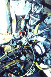
Figure 20. Wiring of the iron components
ready for cathodic polarization.
Figure 21. Positioning of the circulation hose. Although the aluminium components are not directly polarized at this stage they are obviously in some sort of electrical contact to a greater or lesser extent with the iron components and are thus indirectly subjected to some degree of cathodic polarization.
To minimise the risk of cathodic corrosion then, circulation of solution around the object was facilitated by the strategic placement of a hose with outlet holes, attached to a circulation pump. This countered any possible formation of hydrogen bubbles on the surface of the aluminium components (fig. 21).
The PVC flooring material was placed into position as was the stainless steel anode attached to its frame. The engine was carefully lowered into position and potentials measured on various representative parts prior to polarization:
front of engine (ferrous alloy) rear of engine (ferrous alloy) cylinder head (aluminium alloy) baffle cover (aluminium alloy) Table 2: Recorded potentials prior to polarization.
With initial polarization, potentials were then set at:
Table 3: Potentials after initial polarization.
front of engine (ferrous alloy) rear of engine (ferrous alloy) cylinder head (aluminium alloy) baffle cover (aluminium alloy) tank surface Power supply settings were 4.5V and 40 Amps.
Position Potential V/SSE front of engine (ferrous alloy) rear of engine (ferrous alloy) cylinder head (aluminium alloy) baffle cover (aluminium alloy) tank surface The tank and engine were polarized using a single power supply for both. After a short period of instability with fluctuating potentials, power could be decreased to 3V and 20 Amps obtaining stable average potentials of E= -1.33V/SSE for the iron components and a reading of E= -1.60V/SSE for the tank surface. The system was left for four days undisturbed, after which the potentials were checked and the following values obtained:
Table 4: Potentials obtained after four days.
After a further 24 hours of polarization, the power was disconnected and the engine lifted for inspection. Although covered with the white precipitate formed during the solution preparation, all metal surfaces appeared to be in good condition with the precipitate being nonadherent and easily washed off. On reimmersion at the same power settings the potentials obtained were as obtained previously.
The polarization was continued for another 6 days, after which time the engine was removed from the tank and thoroughly cleaned with a high pressure water spray. The surfaces were then kept wet with a water spray. The general appearance indicated that most of the iron concretions were now removed with a small amount of what appeared to be carbonate species still present.
Because of its high pH, the sodium metasilicate solution had to be first neutralized before disposal. This was accomplished using citric acid monohydrate in the proportion of 5g per litre of metasilicate solution. This gave a final solution pH averaging 6.1 which was suitable for drainage disposal. Tanks, hoses, pumps, leads and anode had to be thoroughly cleaned of the tenacious film of metasilicate which formed on all surfaces.
Again a sodium citrate solution, buffered to a pH of 5.4, was prepared in the same manner as for the pretreatment although this time deionized water was used. The total volume of solution was prepared in small open tanks ready for immediate transfer to the treatment tank once the engine was placed into position. This avoided any practical problems which could arise due to delays in the collection of such a large volume of deionized water from a conventional, laboratory water treatment unit.
Since this stage of the treatment is a global one, all major metal components, both aluminium and iron, were wired (fig. 22.), making sure that good electrical contact was achieved. The pump and hose were positioned, as in the previous stage, to facilitate good circulation of the solution.
Figure 22. Wiring of all metal components ready for dechlorination in buffered citrate solution. After transfer of the solution, the engine was positioned in the tank, power connection strategically placed and polarization of both tank and engine immediately commenced.
At the commencement of this treatment stage, as with that previously, one power supply was used for both tank and engine. The initial values were:
tank aluminium parts (average) iron parts (average) Table 5: Initial average potentials for the dechlorination treatment. These values required a power setting of 5.5V and 48 Amps, but these values tended to fluctuate somewhat and the current required seemed rather high. Thus after two days, the circuit configuration was altered to a configuration where two power supplies were used. In this way, the tank was cathodically polarized separately from the engine. The ACORE power supply was continued to be used for the tank and a SODILEC 12V, 30A unit was used for the engine. Potentials were then set at the following values:
tank aluminium cast alloys (ave.) aluminium wrought alloys (ave.) iron alloys (ave.) Table 6: Stabilized potential settings for dechlorination treatment. The potentials remained stable and were maintained throughout the treatment.
During the entire treatment, iron components must be kept at a potential of at least I.lV/SSE or below to avoid corrosion. At the same time the aluminium components should not have a potential of less than -1.6V/SSE, thus avoiding cathodic corrosion. Aluminiumcopper alloys are very sensitive to this type of corrosion below this value, and other alloys to a lesser extent.
Throughout the treatment, samples of the solution were taken at regular intervals to closely monitor pH and chloride ion concentrations, which were determined using a selective ion electrode:
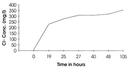
These results can be represented graphically (fig.23).
Figure 23. Increase in chloride ion concentration with time in buffered citrate solution.
Unfortunately due to the limitations of immediate access to adequate analytical facilities, these analyses were only conducted some considerable time after the samples were taken. It was speculated therefore that the erratic variation of Cl- concentrations was due to the presence of chloride-consuming bacterial species.
After approximately 7 days the treatment was discontinued.
Table 7. PH and chloride concentrations for dechlorination treatment.
The engine was removed from the treatment solution and immediately washed with high pressure water spray. The tank and associated equipment were washed and prepared for a final immersion of the engine in tap water under cathodic protection to remove contaminating citrate species.
This was conducted for a period of 24 hours, after which time the engine was removed, washed with water and dried in preparation for the finishing treatments.
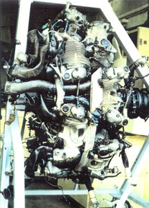
The exterior of the object was dried as quickly as possible using a hot air gun and the interior was pumped out and dried by the same method. A certain amount of superficial mechanical cleaning was conducted prior to the application of a protective surface coating. This was Dinol 4010 which was applied by spray application (fig. 24.).
Figure 24. After the final treatment and the application of Dinol 4010. Finally replacement on its display stand indicated the last phase in the treatment process (fig. 25.)
Figure 25. Comparisons. Engine mounted on display stand. Before treatment. After treatment.
Some 57 items associated with the engine and plane were also put into the care of the Valectra laboratories for treatment and storage/display preparation.
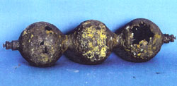
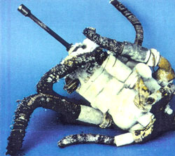
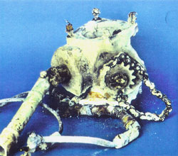
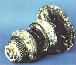
A detailed discussion of the treatment of these objects is the subject of an EDF publication by Ms C. McLennan which is at present in production. However, figures 26 to 31 present an indication of the diversity of the objects treated. Although most of these followed the general plan as described, each treatment was “tailored” to suit the specific needs of the object, taking into account such parameters as construction materials, size, fragility and condition.
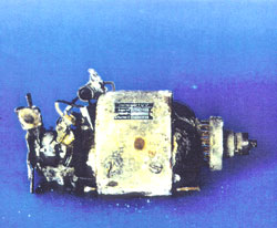
| Figure 26. Oxygen bottle. | Figure 27. Oil pump. | Figure 28. Undercarriage mechanism. |
 |
 |
 |
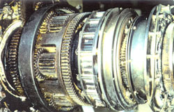
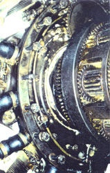
| Figure 29. Clutch component of starter mechanism. | Figure 30. Electrical component of starter mechanism. | Figure 31. Electrical motor. |
 |
 |
 |
 |
Copyright 2021 by TIGHAR, a non-profit foundation. No portion of the TIGHAR Website may be reproduced by xerographic, photographic, digital or any other means for any purpose. No portion of the TIGHAR Website may be stored in a retrieval system, copied, transmitted or transferred in any form or by any means, whether electronic, mechanical, digital, photographic, magnetic or otherwise, for any purpose without the express, written permission of TIGHAR. All rights reserved. Contact us at: info@tighar.org • Phone: 610.467.1937 • JOIN NOW |